Introduction
This book contains learning ressources and tutorials about many of the technologies we used for our participation(s) in the Eurobot contests.
The Eurobot contest is an international amateur robotics contest. The objective is to build an autonomous robot that needs to accomplish a given set of tasks, earning you points.
Through this book, we hope to be able to transfer the knowledge and experience we have acquired during our participation to the team that will participate next year. Our hope is that over the years, this ressource will grow with each participation to become a huge source of information for anyone that wants to participate in the contest.
2018
2019

Organization
When working in a team, it is crucial to have a good way to share files, code and ressources with other members of the team. In this chapter, we explain what tools we used and how we organized our workflow for a good cooperation.
To share code, we use GitHub and git,
we have a shared Fusion360 project to store our 3D models and we have a Google Drive / OneDrive to
store all other files.
We create an office Teams to share all the non-officials files. So everybody have aces to all the information. It was the centralized drive.
GitHub
GitHub is a hosting service for software projects that use git for version control.
GitHub allows us to upload software projects to the cloud in order to facilitate collaboration. You can control who can and can't
contribute to a project and provides tools like bug tracking.
It is important to note that GitHub and Git are very separate things.
- Git is a version control system that allows to keep a history of changes made to source code files
- GitHub is a hosting service that allows to upload Git repositories to the cloud for easier collaboration and sharing
Introduction to Git and GitHub
If you have never used Git or GitHub, we recommend that you get familiar with it. They are incredibly powerful tools. GitHub has a series of simple tutorials that you can follow to get the basics. We particularily recommend to read at least:
- Hello World to learn how to create a repository on GitHub
- Understanding the GitHub Flow to learn how to use GitHub's Web interface to contribute to a project
- Git Handbook to learn the basics of Git and how to do the same as the tutorial above but using Git directly in the command line. Using the terminal may not seem intuitive, but once you understand how it works, it will greatly improve your productivity.
- Forking Projects to learn how to contribute to projects where you don't have write permissions.
Ecam-Eurobot organization
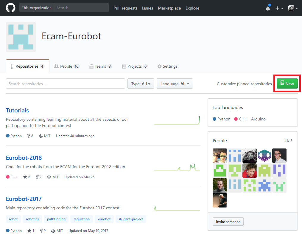
GitHub allows us to create organizations so that multiple users can easily contribute to multiple projects in the organization. We created the Ecam-Eurobot organization to put all our code under.
You can for example find the 2018 repository containing the codes for the 2018 robots, or the source code for this book in the Tutorials repository.
We create a new repository for each year. This allows us to keep old members in the organization with write access to the projects they made and welcome new members with write access to the repository they contribute to.
Administration
To add new members to the organization and configure their permissions, we need an administrator. Each year an administrator is designed who preferably has experience with Git and GitHub in order to help his peers and resolve any Git problems they may face.
This chapter is destined for the person who administrates the GitHub organization
The administrators for past years were:
- 2019 @Diab0lix (Thierry Frycia)
- 2018 @azerupi (Mathieu David)
- 2017 @charlesvdv (Charles Vandevoorde)
You can contact them (most recent first preferably) if you are the chosen administrator for your team. They will add you with the correct privileges.
Creating a new repository
As administrator, your task is to setup GitHub and the repositories so that everyone can work on the project. The first thing you want to do is create a new repository for your year.
We do however recommend to base it off off the repository from previous year instead of starting from scratch. As administrator, head over to the organization's page to create a new repository.
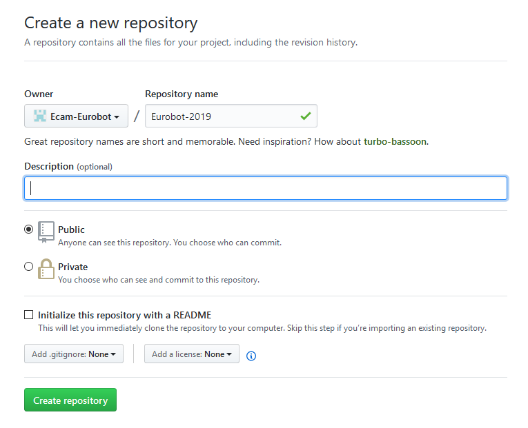
Fill in the name with Eurobot-xxxx where xxxx represents the year. You can add a description if you want. Leave all
the rest blank because we are going to push the code of previous year in the newly created repository.
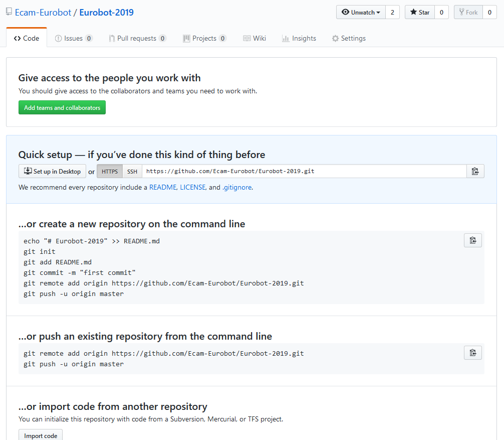
You will land on the following page
Let's push the repository from last year into the newly created repository. On the command line, clone last years repository. In this case, I will clone Eurobot-2018
git clone https://github.com/Ecam-Eurobot/Eurobot-2018.git
cd Eurobot-2018
Now you need to add the newly created repository as a remote. And verify that it was added correctly.
git remote add next-year https://github.com/Ecam-Eurobot/Eurobot-2019.git
git remote -v
Push the repository into the newly created repository
git push -u next-year master
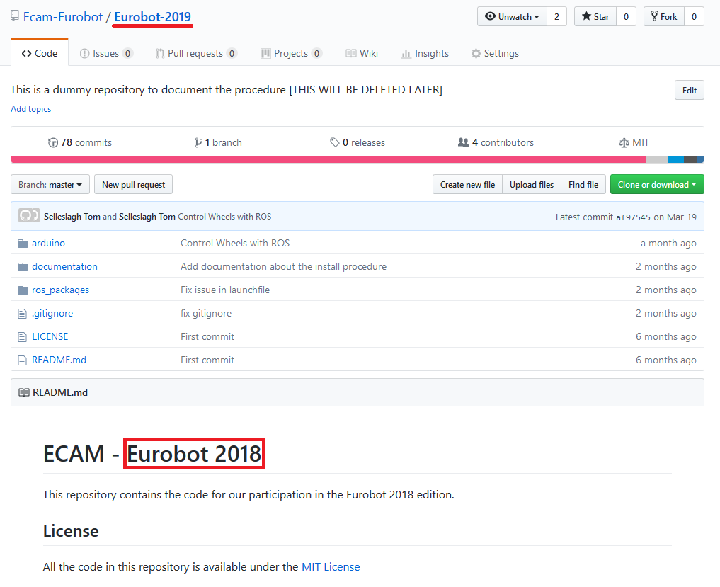
If we refresh the GitHub page for the newly created repository, we can see something similar to below.
We can see (in the top left) that we are in the new repository and if we look at the README at the
bottom we can see that it contains the files from previous year. We can now start to work in the new
repository without affecting the old one.
Note:
Now that the new repository is created, you can remove your local clone of the repository from last year. You will not need it anymore.
Adding teams
Now that the repository is created, you need to add two teams to the Eurobot organization:
- Eurobot <year>: this team will contain all the members participating this year. We will give this team the privileges to push to any branch except the master branch.
- Eurobot <year> Reviewers: this team will be given more privileges. They will be able to review and accept pull requests to the master branch.
Note:
The master branch should always be kept in a working state, this is the golden rule! As administrator, with help from the reviewers, it is your duty to make sure that this rule is followed by everyone. The normal development process should be the following:
- For any new development a new branch is created by the member that develops it
- He implements the new feature / behavior
- When done, he creates a pull request against the master branch
- At least one reviewer reads the changes, makes sure that the code meets the quality guidelines and aproves the changes
- Only then can the code be merged into the master branch.
Resist the urge of merging code that hasn't been reviewed.
To create a new team, go to the GitHub organization: Ecam-Eurobot and go to the "teams" tab.
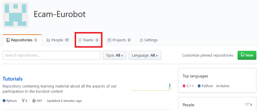
Then click the "New team" button, fill in the name as mentioned above and then click "Create the team".
Give them correct permissions
Now that the teams are created, we need to give them the correct permissions. Go to the newly created repository, under "Settings" go to the "Collaborators & Teams" section.
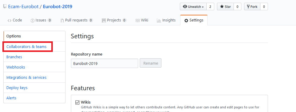
Then add the teams you created with the write permissions, like below.
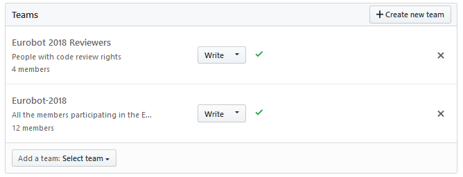
Now go to the "Branches" section and add the master branch as a protected branch.
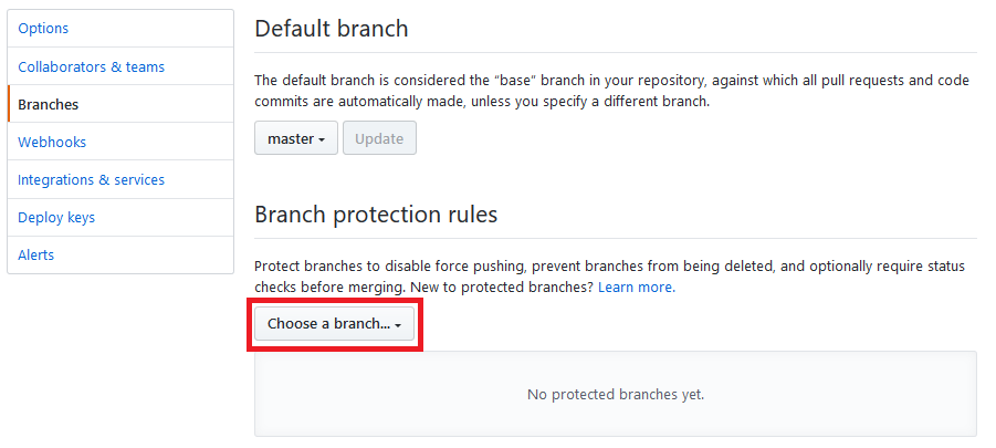
And configure the protections like in the image below:
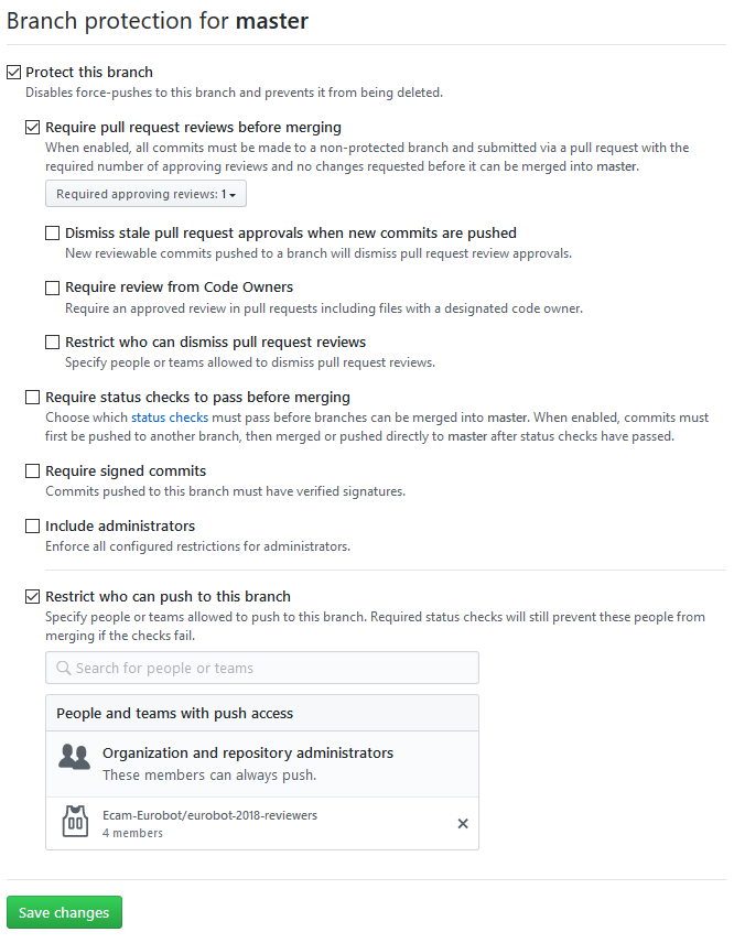
This will prevent anyone from commiting to the master branch directly except the administrator and the reviewers, who need push access to accept pull requests. Don't abuse these privileges, it is always better to have your code reviewed by others, even if you are a badass programmer!
Invite members
Now that everything is setup, we still need to invite the people who will be participating with you this year and assign them to the correct teams. To do this, go to the organization's page again under the "People" tab and click on "Invite member".
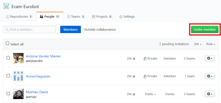
Type in their GitHub user name and invite them. In the invitation, you can already assign them to the correct teams.
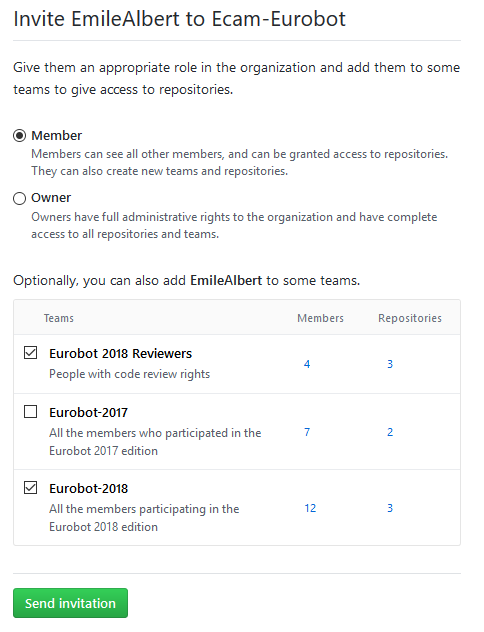
Once the invitation has been sent, the invited user can accept the invitation by visiting the organization's page: https://github.com/Ecam-Eurobot.
mdBook
To generate this online documentation "book", we use a tool called mdBook. This chapter will briefly introduce this tool in order for anyone to be able to contribute and improve this document.
The official documentation for mdBook can be found here
Structure of a book
A book has the following structure:
book-test/
├── book.toml
├── book
└── src
    ├── chapter_1.md
    └── SUMMARY.md
The book.toml file contains the configuration options of the book.
In this file you can find the title, the authors, but also an option to enable math equation rendering, etc.
For a list of the options, refer to the official documentation. The book.toml file also represents the
root folder of the book. When we run mdBook, we need to either run it in that folder or point it to that folder.
In that same folder, you can find 2 folders: src and book. src contains the source files, written in markdown.
When running the tool, it will take all the files in that directory and compile them into the book which is then stored in the book folder.
Finally, the most important file is the SUMMARY.md file. This file represents the table of content of the book, giving the hierarchy of all the
chapters and where to find their source files. The folliwing is an extract from this books summary file.
# Summary

[Introduction](introduction.md)
- [Organization](organization/organization.md)
    - [GitHub](organization/github.md)
        - [Administration](organization/gh-admin.md)
    - [mdBook](organization/mdbook.md)
- [Mechanical](mechanical/mechanical.md)
    - [3D modeling with Fusion360](mechanical/fusion.md)
    - [3D printing](mechanical/3d-print.md)
    - [Mecanum wheels](mechanical/mecanum.md)
We can see that it is simply a set of nested markdown lists containing links to the source files.
Markdown
The source files for the book are written in Markdown, which is a very simple markup language. You can learn the basics in '60 seconds'.
Syntax highlighting
To insert code blocks with syntax heighlighting, use triple backticks followed by the language name / abreviation:
```python
import sys

sys.exit(0)
```
This will generate the following:
import sys

sys.exit(0)
Images
In mdBook, paths to images should always be referenced from the src folder. So if you image is located in src/img/my-image.png,
you should use .
Generating the book
When you make changes locally, you probably want to see how it looks before making a commit. You can install the tool for this. At the time of writing, [pre-built binaries] exist for Linux and MacOS, but not for Windows.
For windows, I have compiled a binary that you can use. You can also compile mdBook from source, but this falls outside the scope of this tutorial.
When you have mdBook, add it to your path so that you can use it in the terminal / command line from anywhere. For this, I will refer you to external documentation: Linux / MacOS & Windows.
Now everything is setup, you should be able to open the terminal / command line and type mdbook --help and see the following:
mdBook --help
mdbook v0.1.5
Mathieu David <mathieudavid@mathieudavid.org>
Create a book in form of a static website from markdown files

USAGE:
    mdbook.exe [SUBCOMMAND]

FLAGS:
    -h, --help       Prints help information
    -V, --version    Prints version information

SUBCOMMANDS:
    build    Build the book from the markdown files
    clean    Delete built book
    help     Prints this message or the help of the given subcommand(s)
    init     Create boilerplate structure and files in the directory
    serve    Serve the book at http://localhost:3000. Rebuild and reload on change.
    test     Test that code samples compile
    watch    Watch the files for changes

For more information about a specific command, try `mdbook <command> --help`
Source code for mdbook available at: https://github.com/rust-lang-nursery/mdBook
The two command that are the most interesting for you are build and serve.
Running mdbook build in the folder where the book.toml is located will generate the book.
The generated book can then be found in the book/ folder.
Running mdbook serve is even better, because it will watch the files for any changes and rebuild the book automatically.
On top of that, it serves the book on http://localhost:3000 and automatically refreshes the browser after regenerating the book.
You launch it once, when you begin to write and forget about it. It is that simple.
Hosting
When you visit the following address: https://ecam-eurobot.github.io/Tutorials/ you can find this book online.
To host the website, we use GitHub. In the repository of the book, there is a branch called gh-pages. This is a special branch that can be used to host a
static website through GitHub.
When you push a new version of the generated book to this branch, it will be accessible online from the address above.
Note:
Don't push manually to this branch. As explained below, a new version of the book is generated and pushed automatically on each new commit on the master branch!
Travis
We have setup Travis to generate the book for each new commit on the master branch. This means that the hosted book is always up to date, with a couple of minutes delay.
The travis configuration file looks like the following:
sudo: false
dist: trusty
language: rust      # We want to download the Rust toolchain (because mdBook is written in Rust)
cache: cargo        # We want to cache the cargo folder to speed up the compilation of mdBook
rust:
  - stable
branches:
  only:
  - master          # We only want to execute Travis for commits on the master branch
before_script:
  - (cargo install mdbook --vers ^0.1.5 || true)    # Install mdBook (the || true trick is to avoid an error if it is already installed)
script:
- mdbook build      # Generate the book

# Deploy the book to GitHub Pages
deploy:
  provider: pages
  skip-cleanup: true
  github-token: $GH_TOKEN  # Set in travis-ci.org dashboard, marked secure
  keep-history: true
  local-dir: book
  on:
    branch: master
Mechanical
As every year, a big part of conceiving the robot is designing the mechanical parts. The requirements change with the years, but as a big innovation in 2018, we suggest to keep the Mecanum wheels system. According to the rules, you'll have to realize diverse action in order to get points.
For example, in 2018, the actions were:
- Collecting blocs, lift them, sort them according to their color and build a tower with them.
- Collecting balls from a pipe, sort them by color and evacuate them to a lower position and to a higher one.
You'll find more information about the designed mechanisms in the two dedicated chapters (Lift & Ball mechanism).
Before that, we want to introduce you to one of our main tools to design those mechanisms and build them. These are:
- Fusion 360, to design 3D models.
- 3D Printing, to make the pieces we designed or found on the internet fast and cheap.
1. Getting in touch with Fusion360
Fusion360 is a 3D modeling software used by many professionals and hobbyists to create pieces. You can directly send your models to slicers in order to print them or export the 2D plans to build it your own. The following chapters should give you a global overview of how Fusion360 works and what you can use it for. We'll try to orient our writing to learn your to design in order to print your models later and will end with some tips about the printing them.
To complete your learning we strongly recommend you subscribe to Lars Christensen's Youtube channel. He's a master in the use of Fusion360 and has very well made videos about every problem or question you might have.
3 videos in particular should hold your attention to get started: Fusion 360 Tutorial for Absolute Beginners— Part 1 and of course Fusion 360 Tutorial for Absolute Beginners— Part 2 and Fusion 360 Tutorial for Absolute Beginners— Part 3.
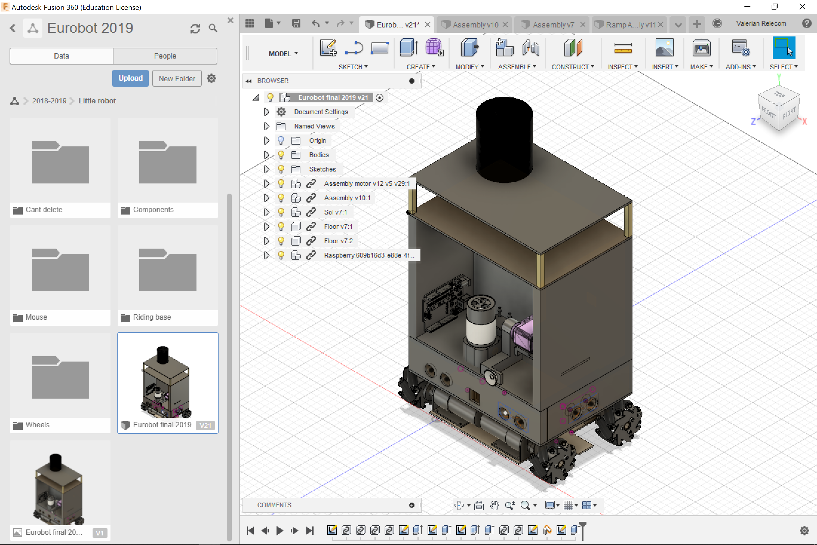
With all these tools in hands we were able to design our robot: Cortex.
Fusion360 environment
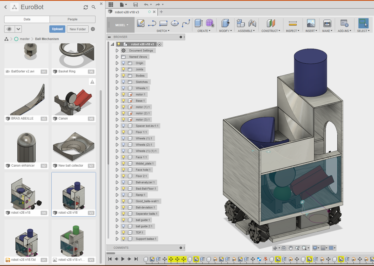
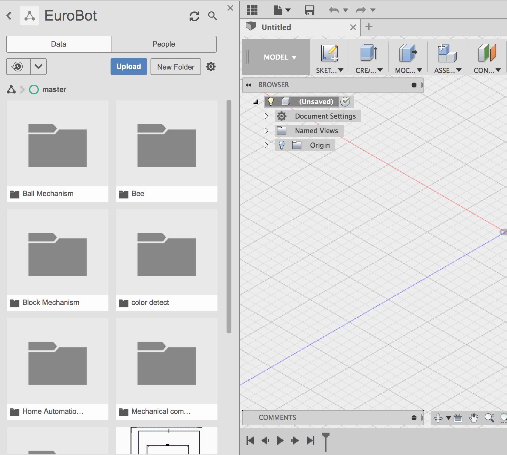
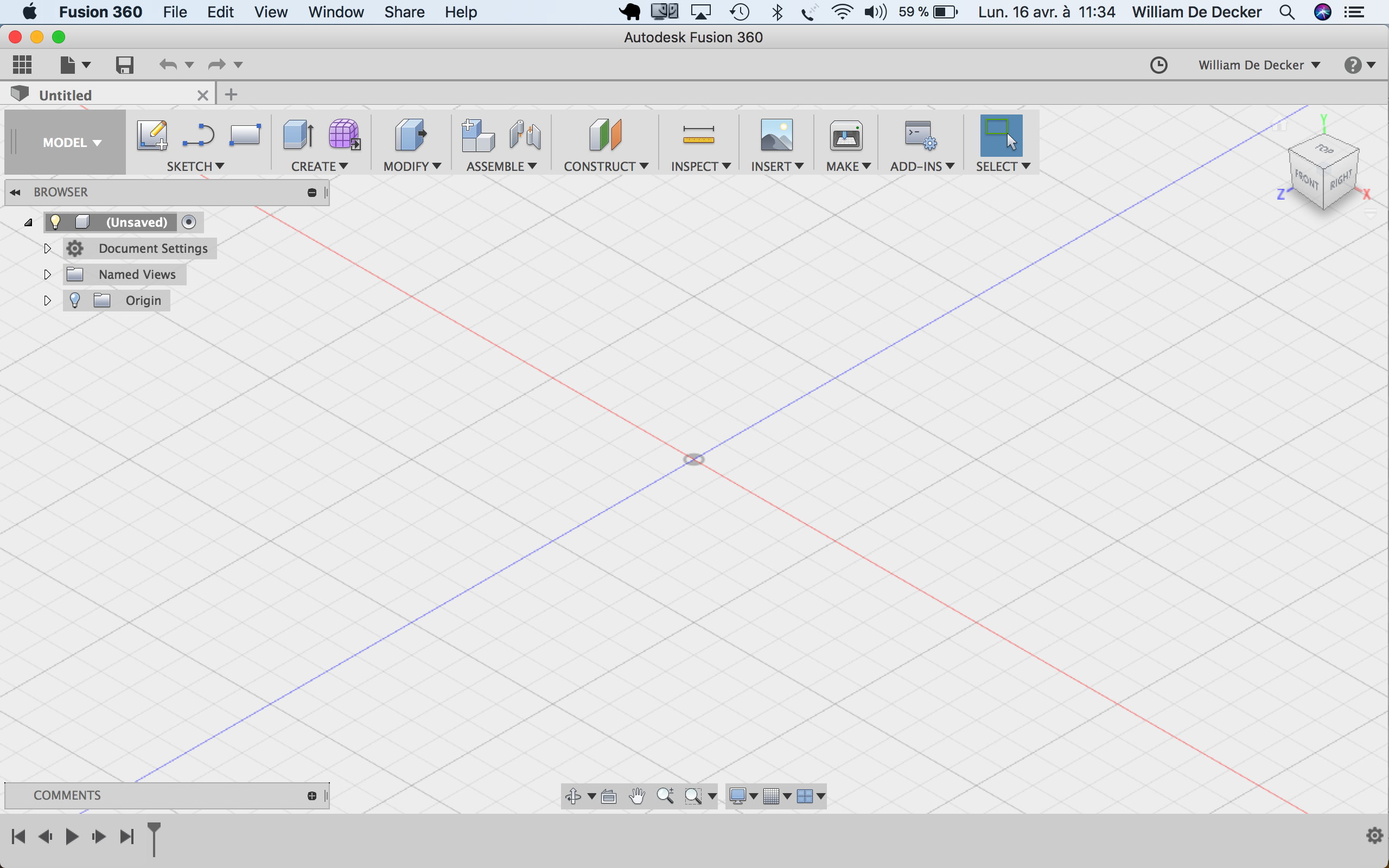
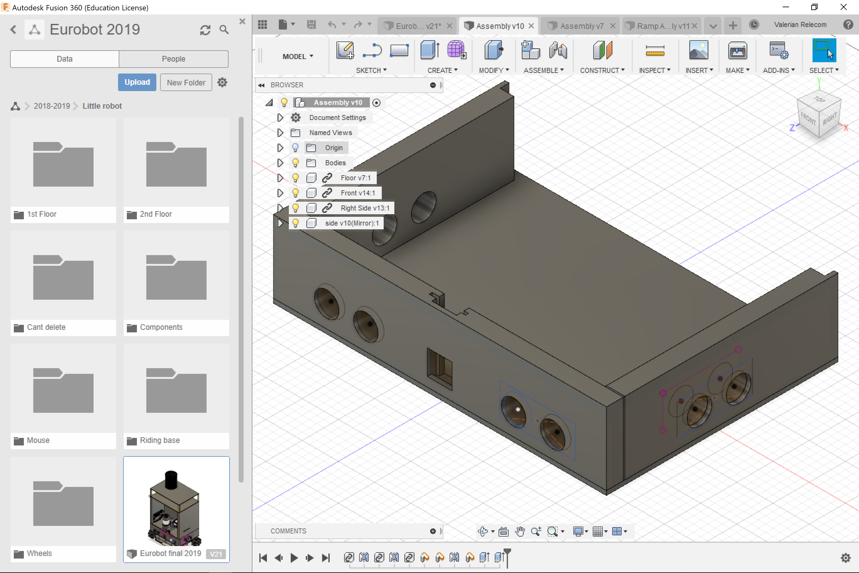
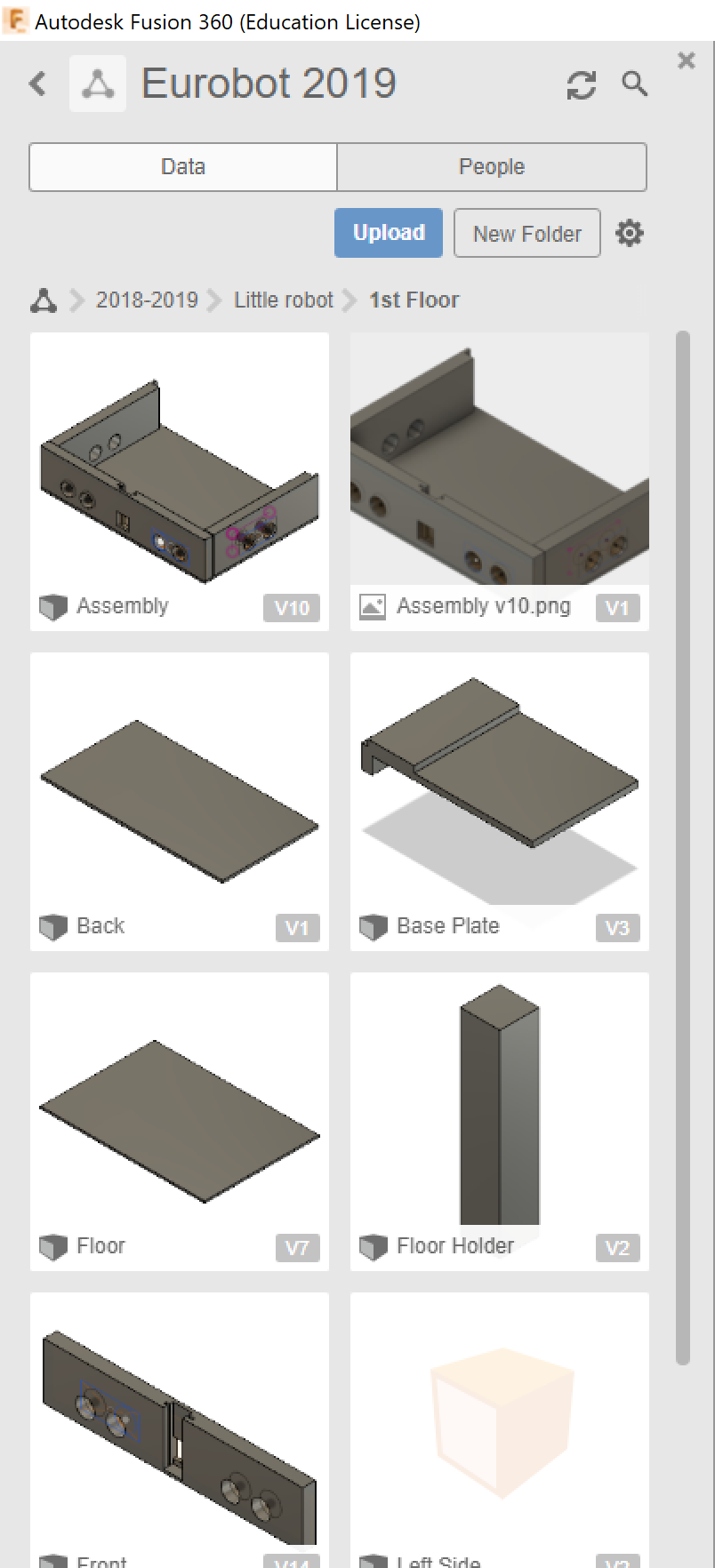
The first window you get when opening Fusion360 should be this.
By clicking on  you access to the repository holding all your folders.
A good practice is to sort them into other repositories according to their relevance. A little bit like you would sort your computer desktop.
you access to the repository holding all your folders.
A good practice is to sort them into other repositories according to their relevance. A little bit like you would sort your computer desktop.
Project view
We'll let you listen to M.Christensen by clicking on the links to the videos we gave earlier to learn the basics of Fusion360. He's an expert on the subject and honestly the only good way to learn this kind of software is by watching someone do and copy. Please don't learn the shortcuts by heart, you'll learn the most used ones by practice.
2. Main Functions and Shotcuts
You should already be able to do your first model now, but in case you misted some of the many things explained by Lars, we would like to give you a quick recap.
To start, note that all functions are easily available trough the "s" key shortcut. Just type a word related to what you are searching for and you'll probably find it directly. Note that you can save them by clicking on the curved arrow.
2.1. Shortcuts
Please don't study them, by the way you probably know most of them after your first hour of practice . If it's still not the case, you'll find them here:
- S=Model Toolbox
- L=Line
- C=Circle
- X=Construction
- D=Dimension
- Q=Push/Pull
- M=Move
- J=Joint
- T=Trim (delete lines)
- Middel button of your mouse = Pan
- Maj+ middel button = 3D move
2.2. Useful functions
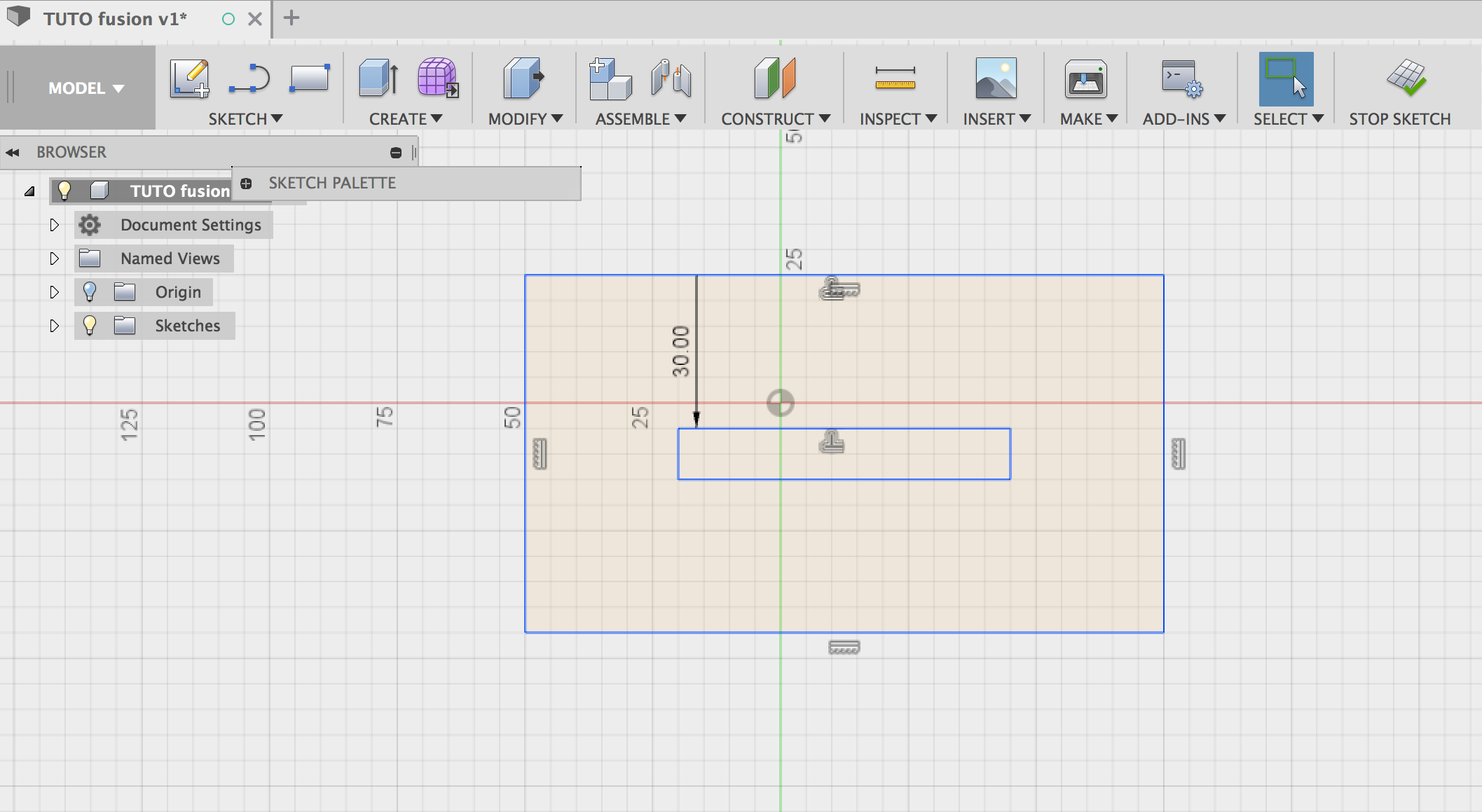
Offset
Offset is a very handy tool when it comes to drawing parallel lines.
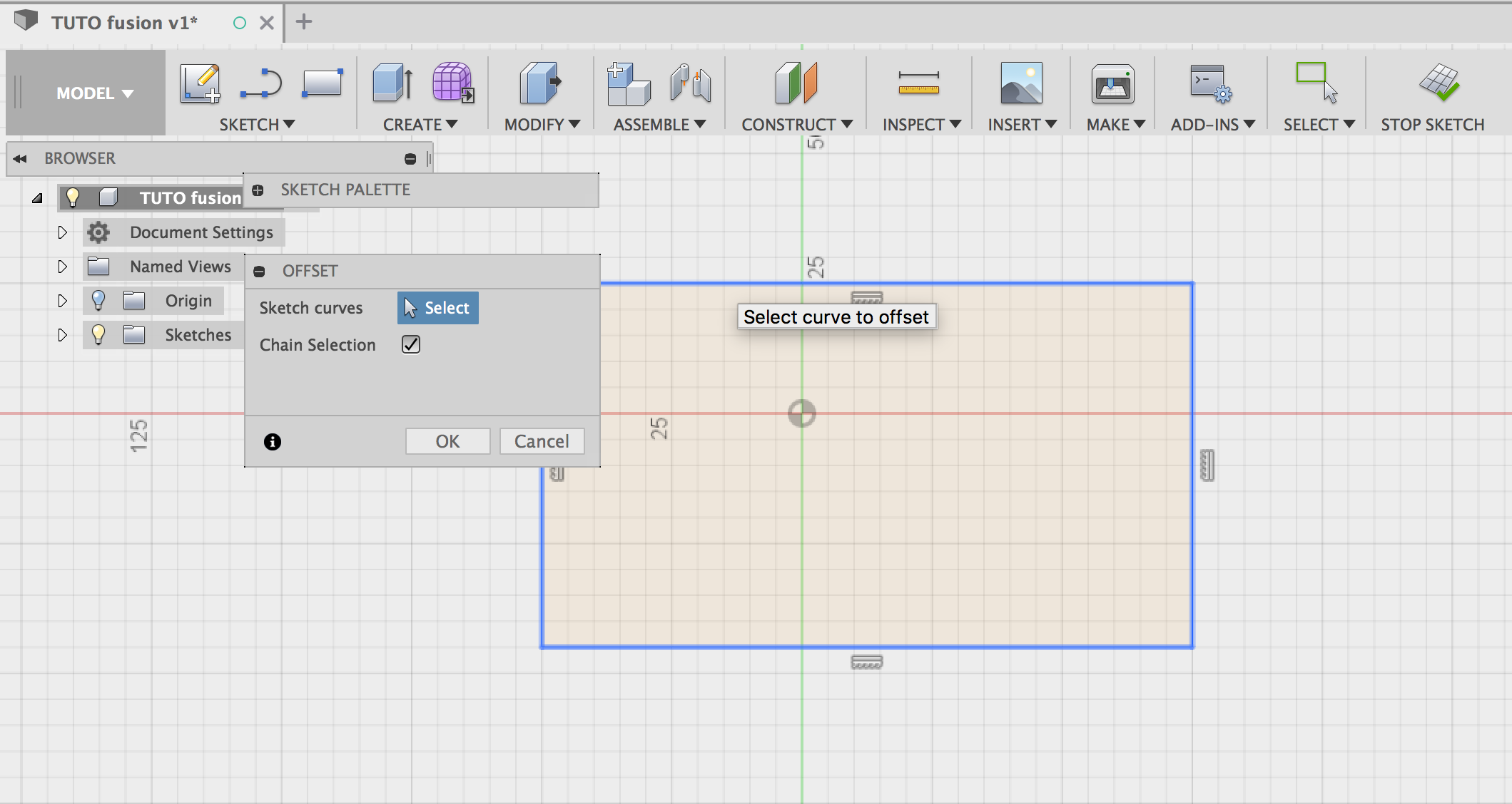
The tools works only in sketch mode and you have to already have a reference line (or a shape).
Type the "o" key to open the "offset menu", you then have to select the reference line you want.
You can either drag and drop the cursor with your mouse or type the value you wish the offset to be.
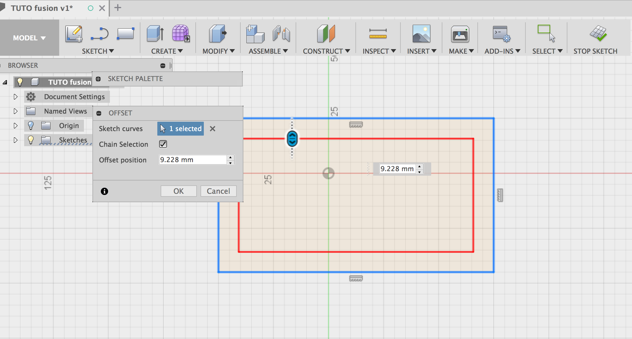
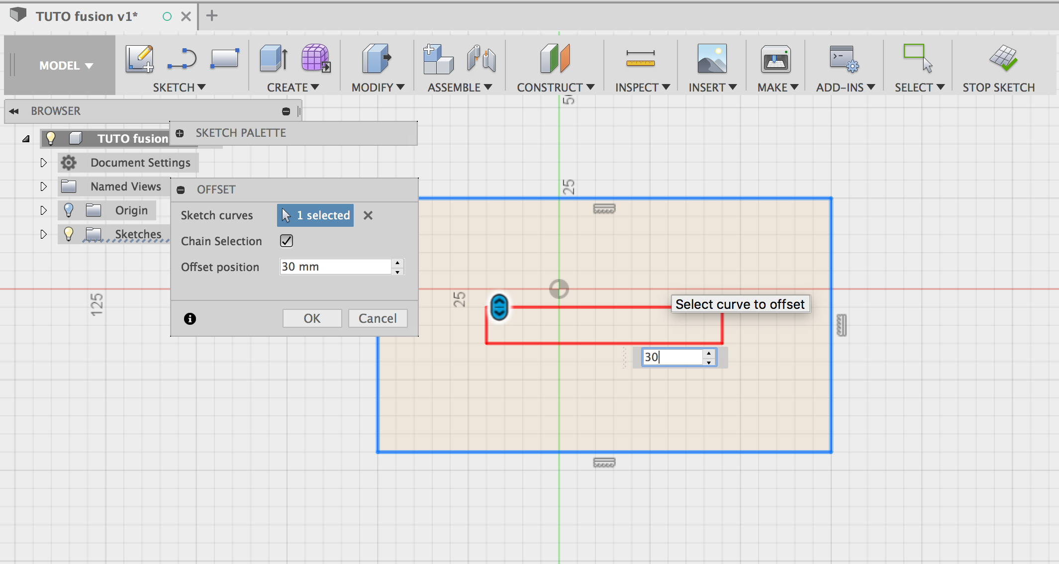
You'll end with the line/shape you selected offset as you wanted.
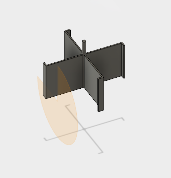
Sweep
Another useful tool to make pipe, slide and so on is the "sweep" function. Start by drawing a sketch on a
face. In our example it's going to be a double circle.
Then close your current sketch. Go to another face. Start a new sketch . Use "spine" for example and draw a line following as much point as you want.
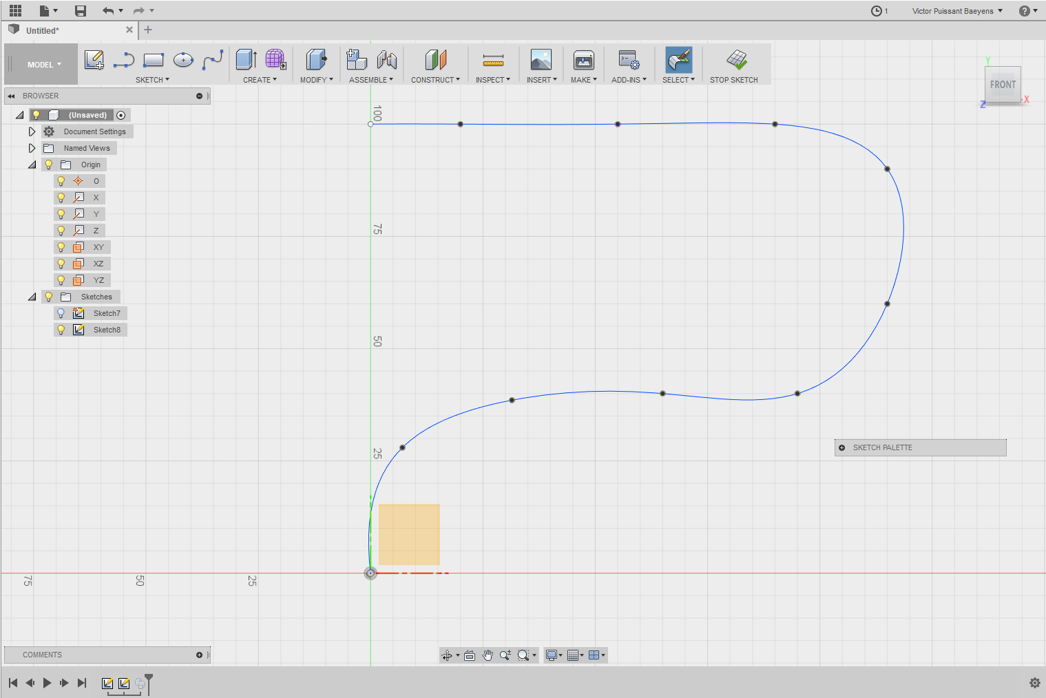
You'll be able now to use "Sweep", select the space between the two circle as "profile", select the line as "path" and you'll automatically make a curved pipe!
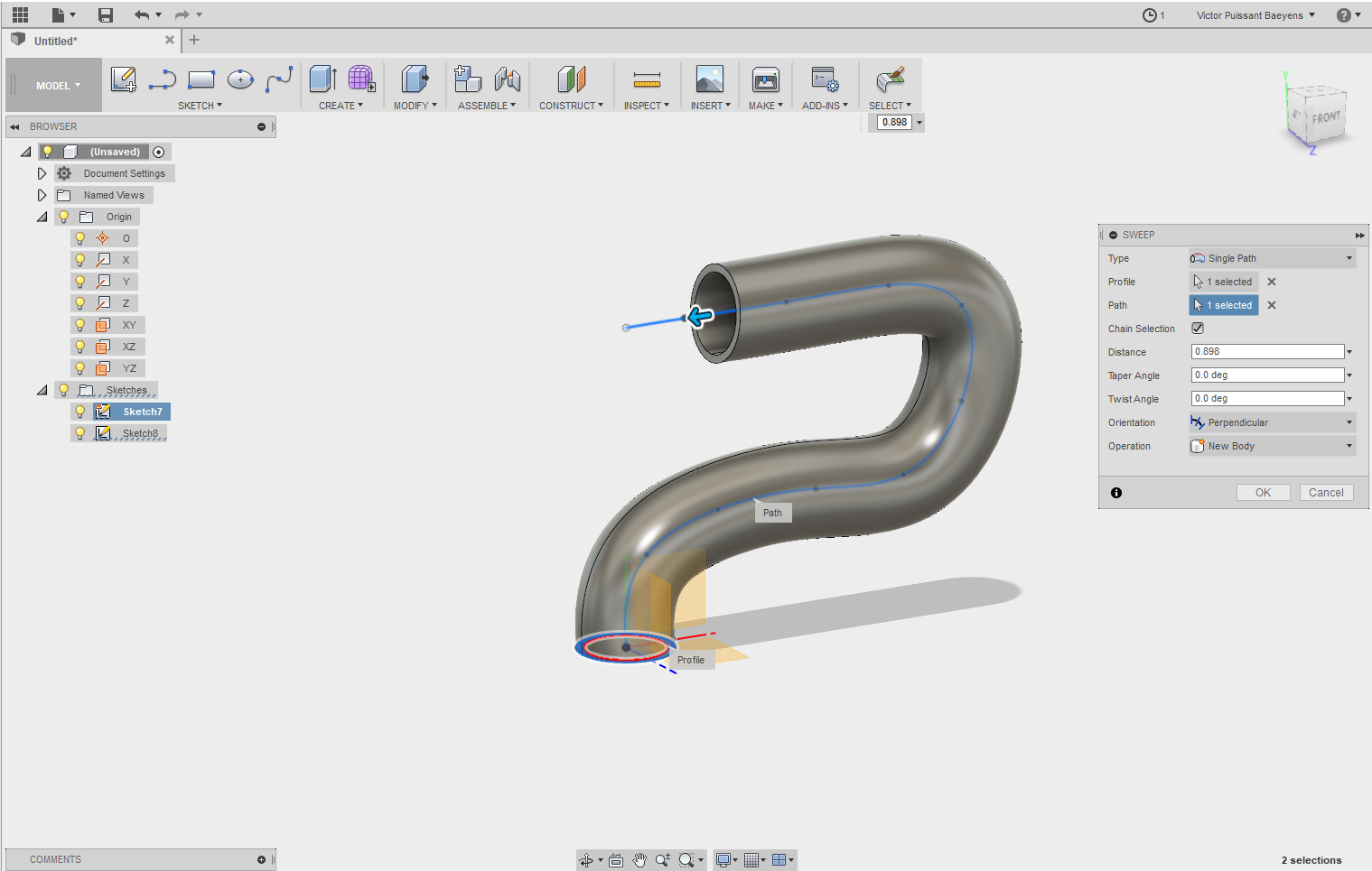
We used it for example for the slide in the 2018's ball mechanism.
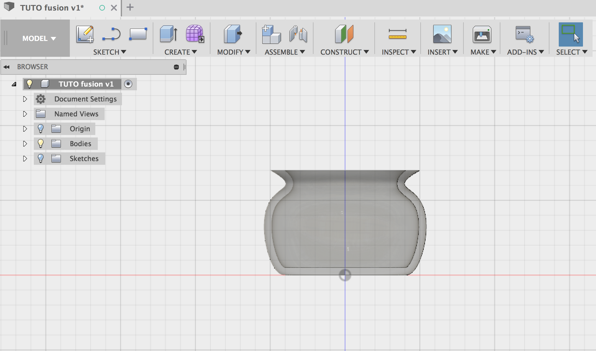
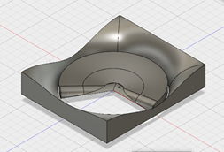
Revolve
Revolve allows you to create objects as if you turned them on a lathe. It comes in handy to make wheels, cannons, ...
To used it you have to first create a shape around an axis. When you create that shape, you have to imagine it round. So you only have to draw "a half cut of your future object".
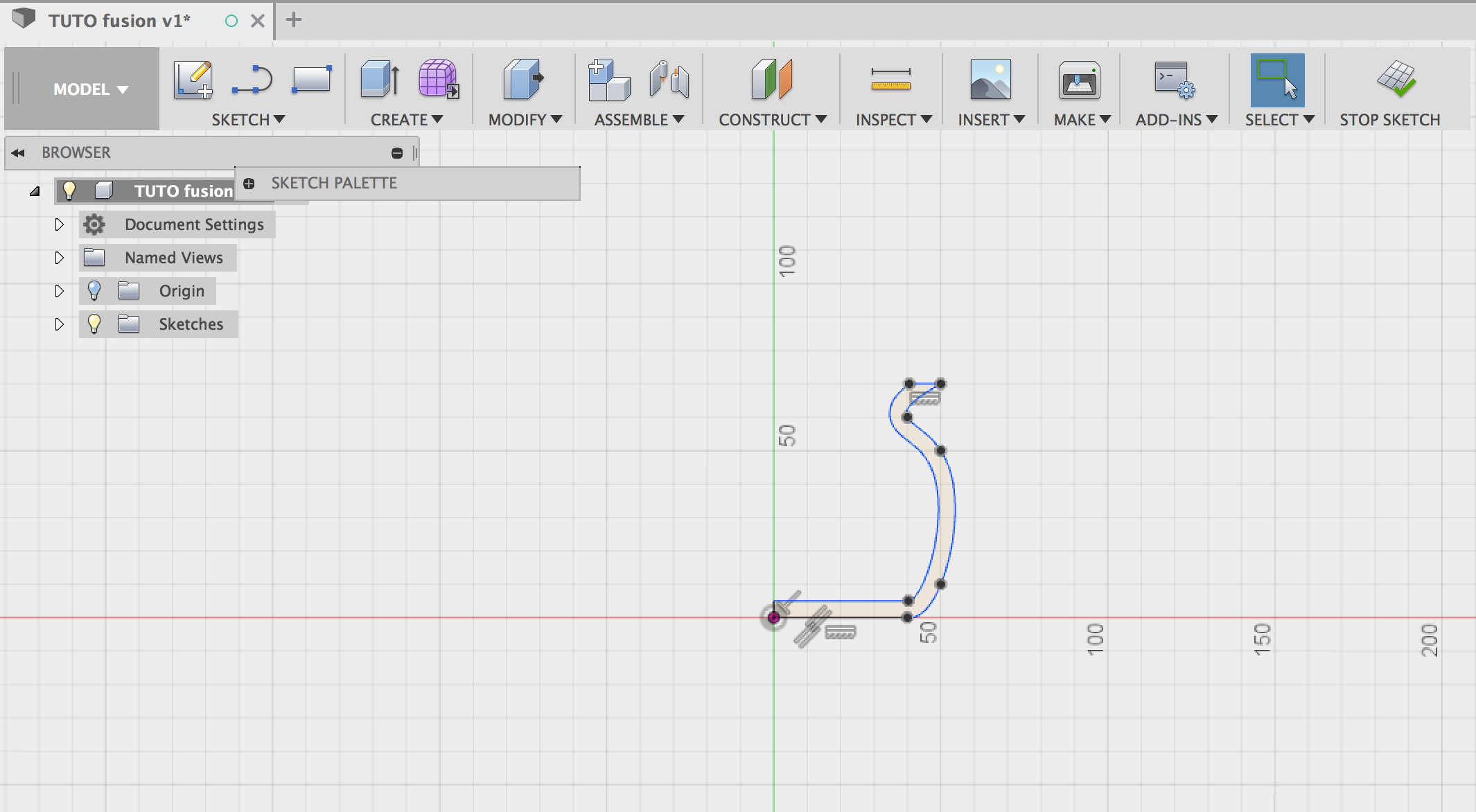
Type "s" to access the "search menu" and enter "revolve" to find the tool. You'll have to select the shape and the axis you want and press "enter".
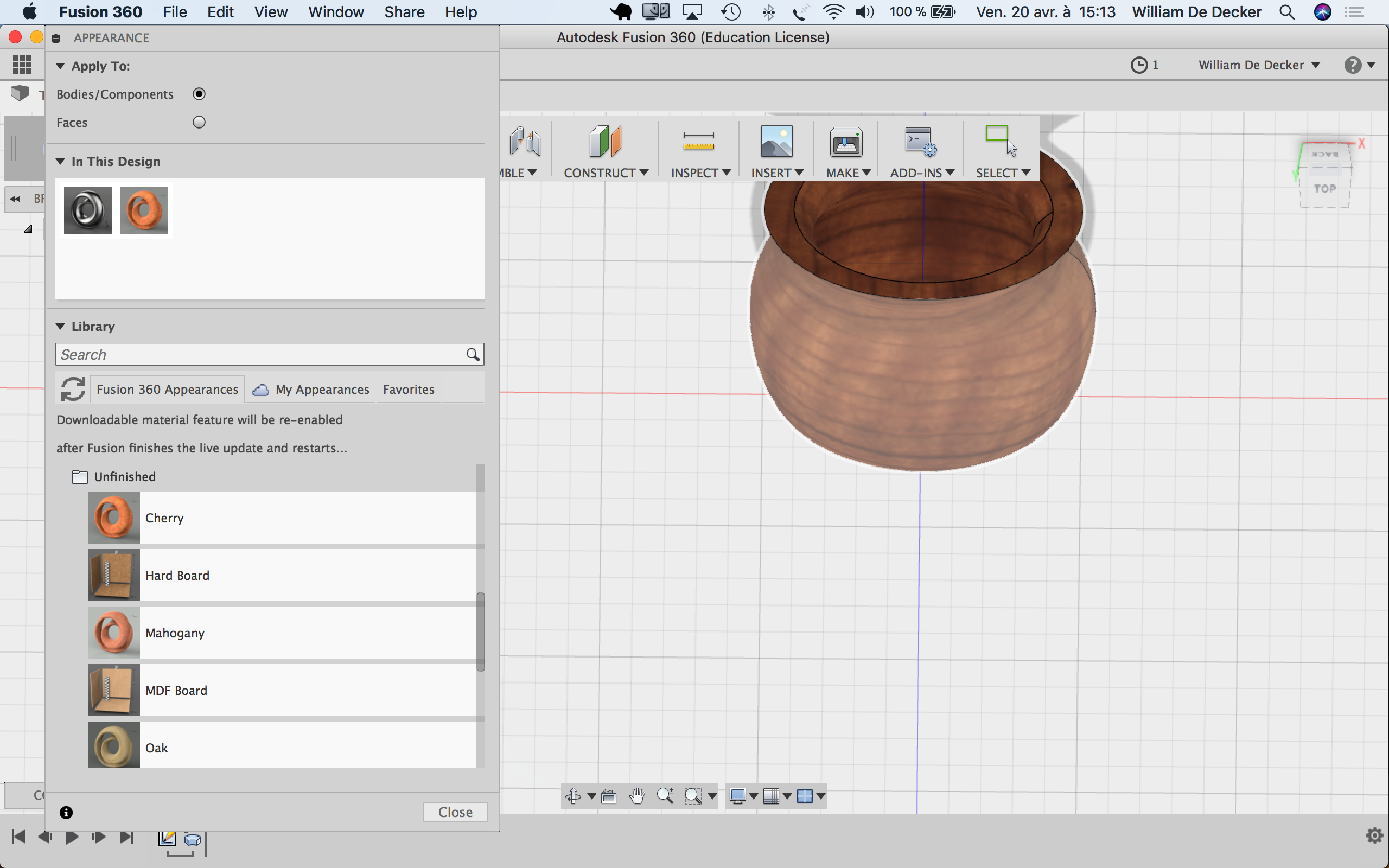
Appearance
To make design easier for others to imagine or simply to choose colors and material purely esthetically, the "Appearance" tool is a must! You can archive more or less the same result with the "Physical Material" tool, but this is more often used for simulation. You can also combine those tools to get for example a steel pipe covered in leather without having to create the wrapping in a new component. It is also very handy when creating complex assemblies with little pieces because the different appearances help to see those different pieces.
Appearance is really easy to use. Type "a", choose the look you like and drag-drop it on the body you want. You can directly drop it in the project tree or on the visual objet.
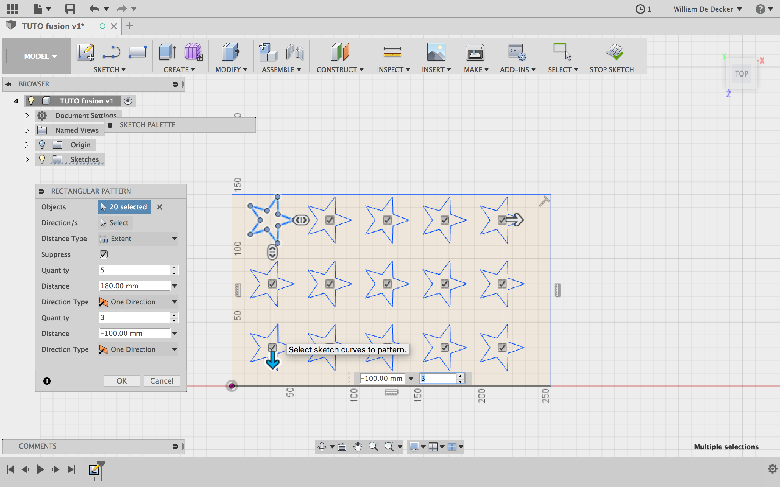
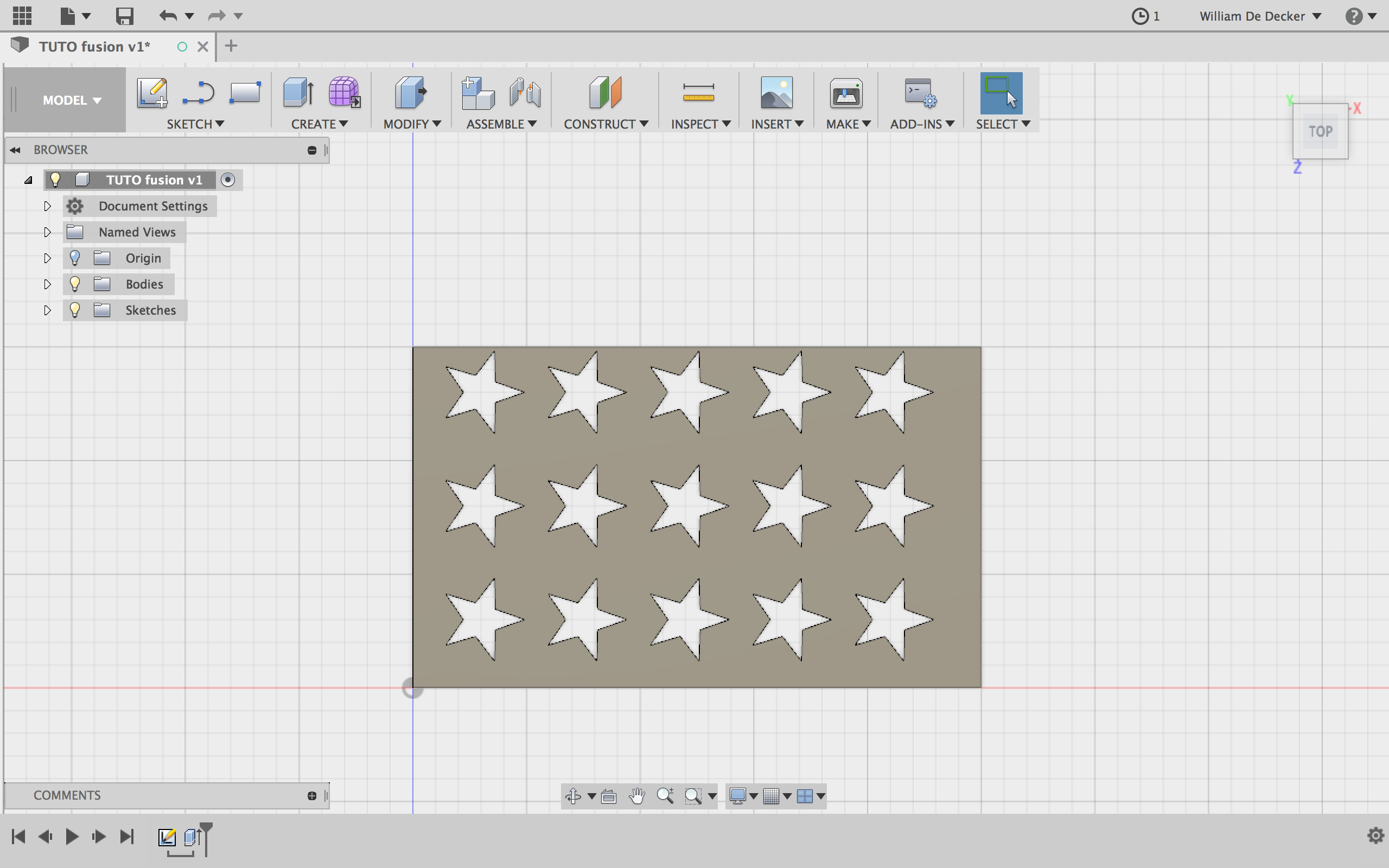
Pattern
Real time savior, "Pattern" allows you to duplicate sketches, bodies and components on a given distance.
Multiple pattern tools exists. To see then go into the "search menu" and type "Pattern".
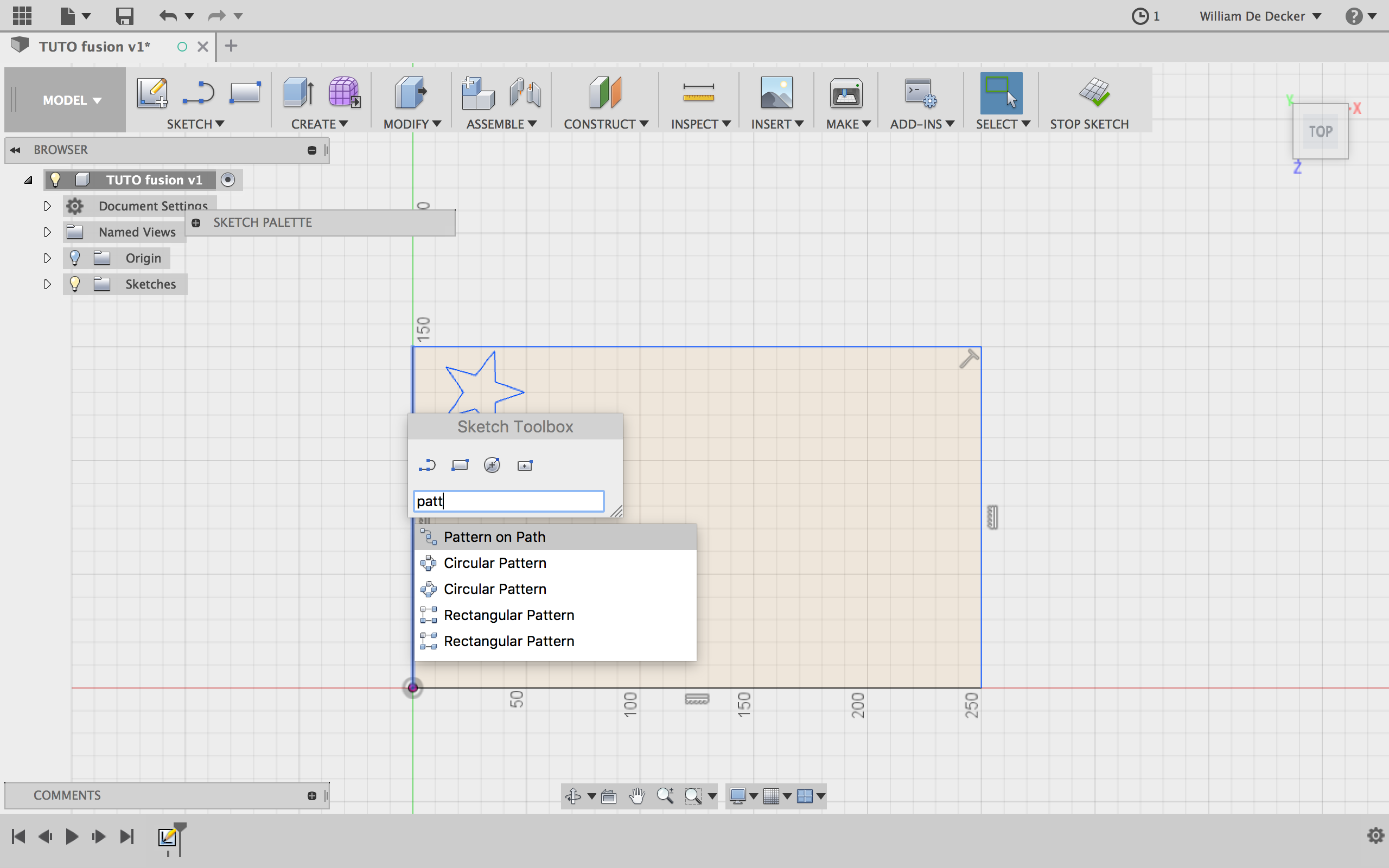
As you can see in the above picture, you can create a circular, rectangular or "free style" pattern. For both rectangular and circular patterns the ones with white square create patterns in sketches. The grey ones create patterns of volumes (bodies, components). We'll only present the sketch pattern, but the volumes work in a similar way.
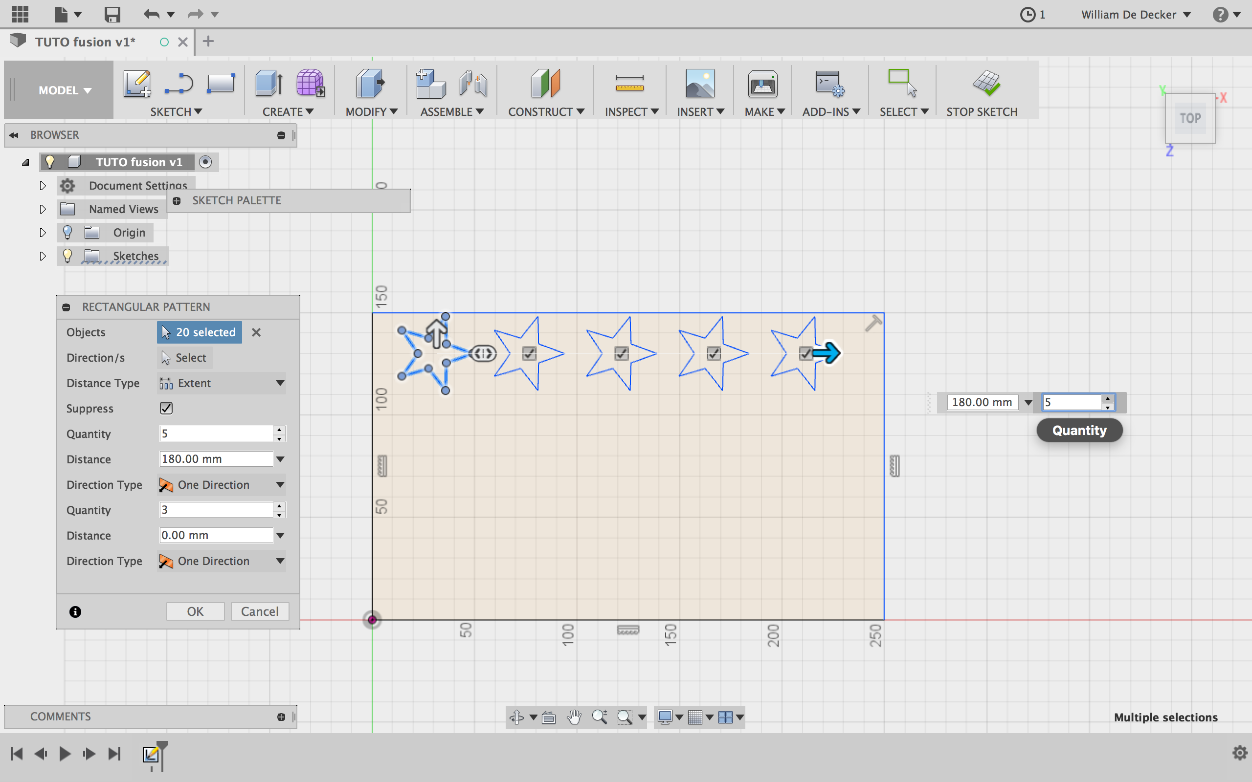
Rectangular pattern
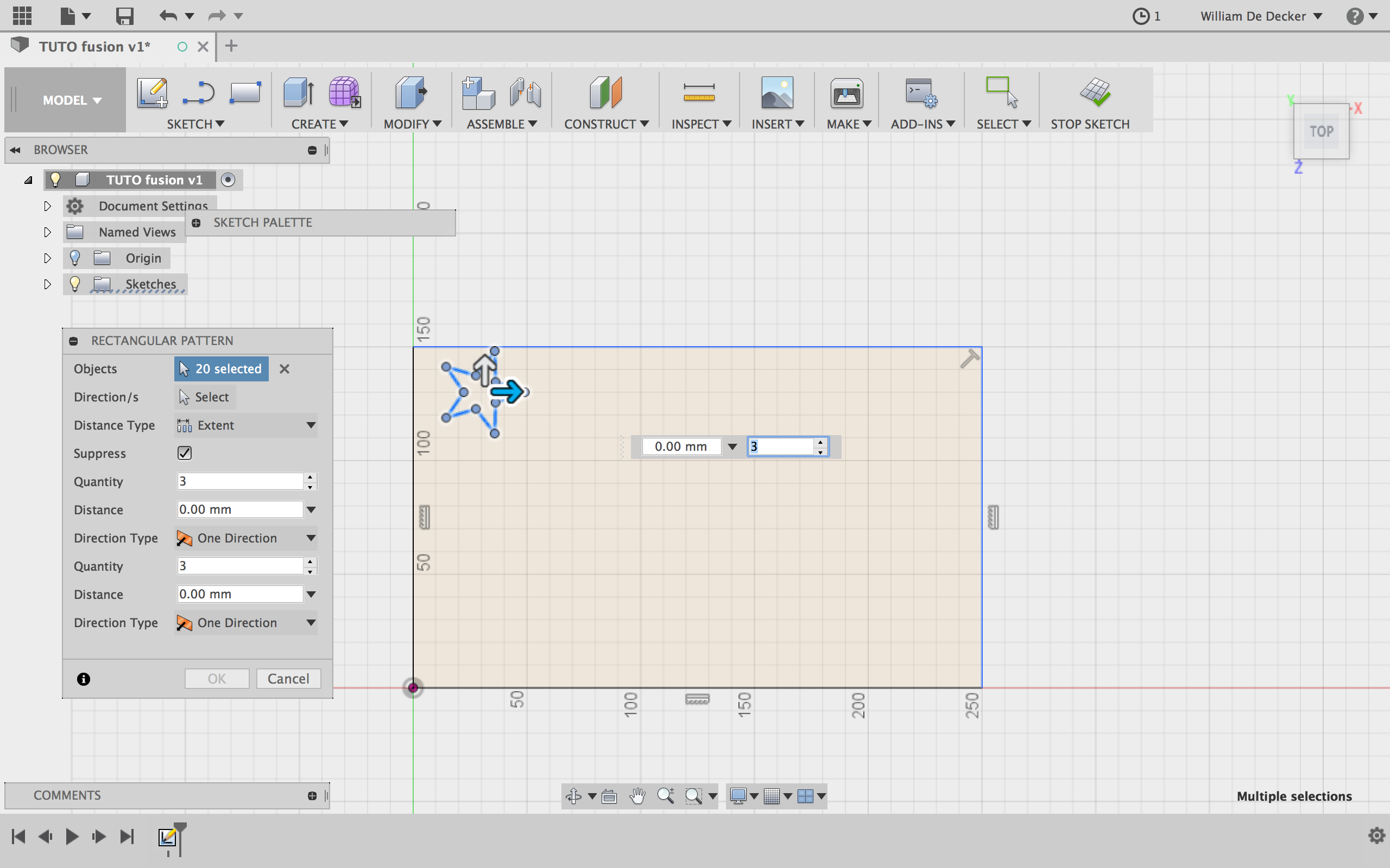
To apply rectangular patterns, select the desired shape and the amount of copies you want in the 2 directions. You can then enter (or drag-drop) the distance on which you want to copy that shape for both directions and click "ok".
Circular pattern
Circular patterns work in a similar way accept the fact you have to choose a center point and you can choose to make a complete revolution around it, or on a given angle.
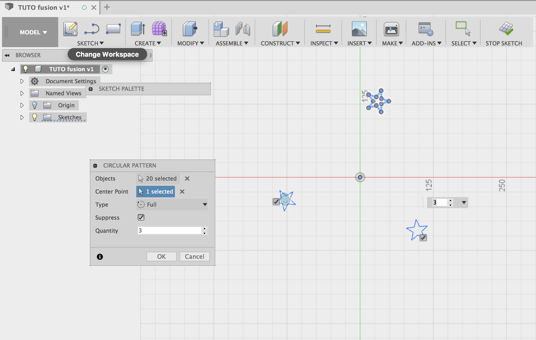
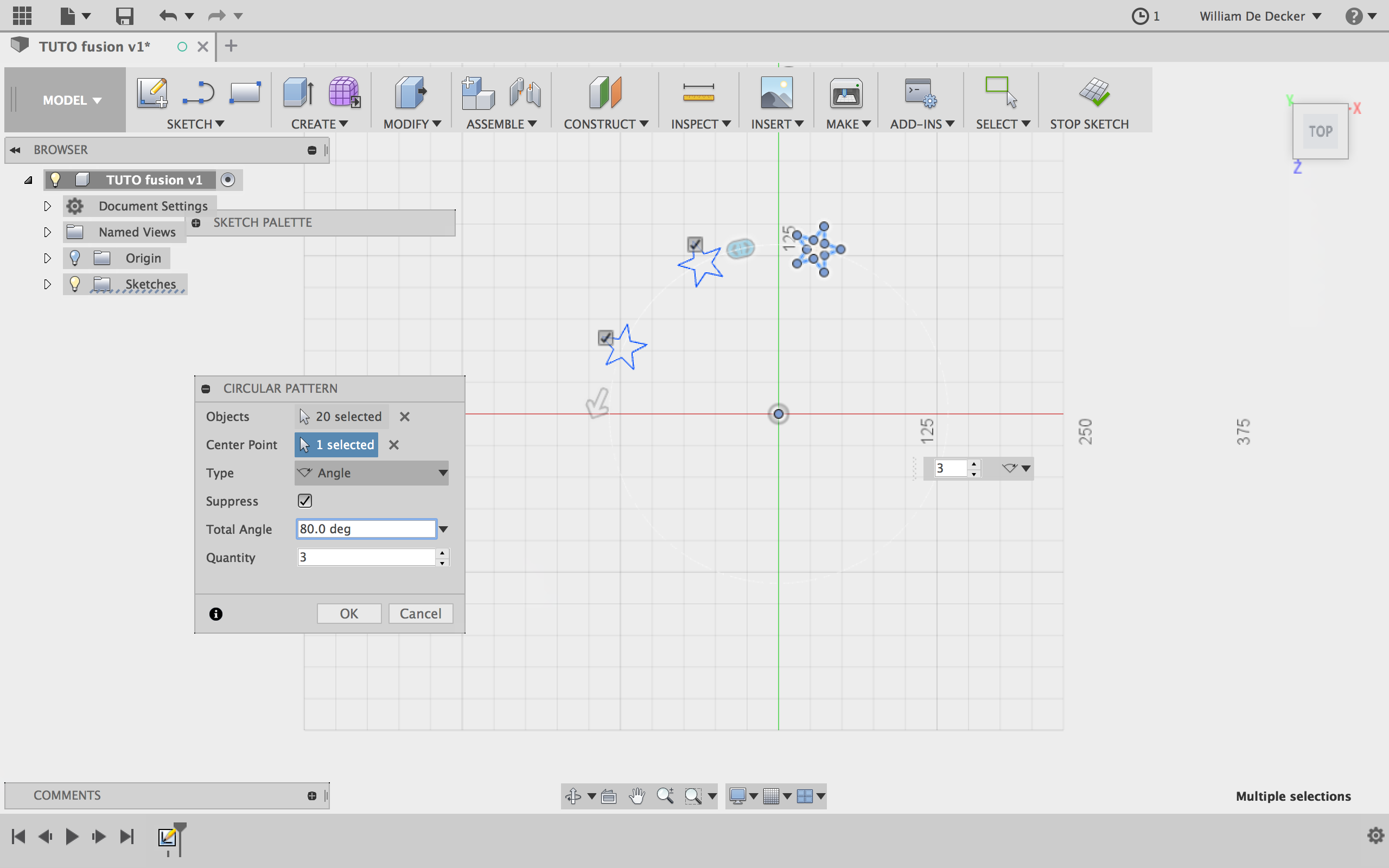
Note that it's also possible to draw a path and then follow it with our pattern.
Mirror
Available in sketch and also in 3D, the "Mirror" tool is very useful to create quickly twice the same things symmetrically from a line or a plane.
For the 3D tools, start by drawing your piece, in this case a notch to close a wall.
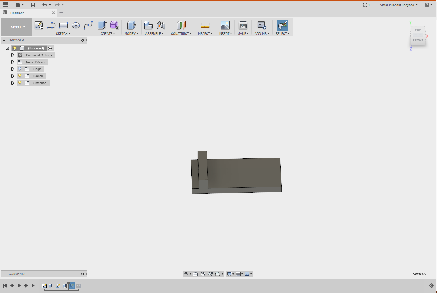
Use the Mirror tool, select the faces that you want to copy and then the plane.
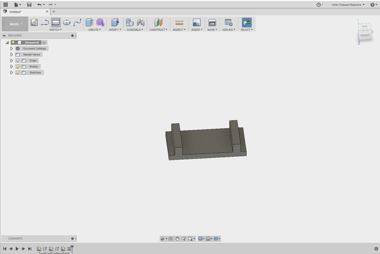
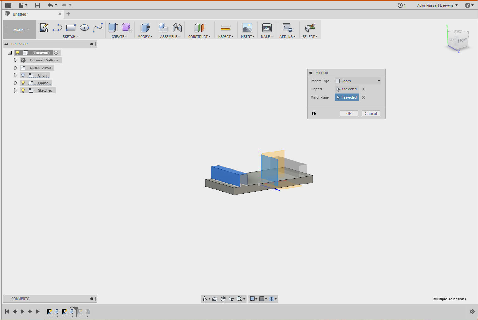 Note that if you select only the top face of your notch you won't be able to copy it because the program doesn't allow you to create a new face in the empty space. You have to select all the three faces of your notch.
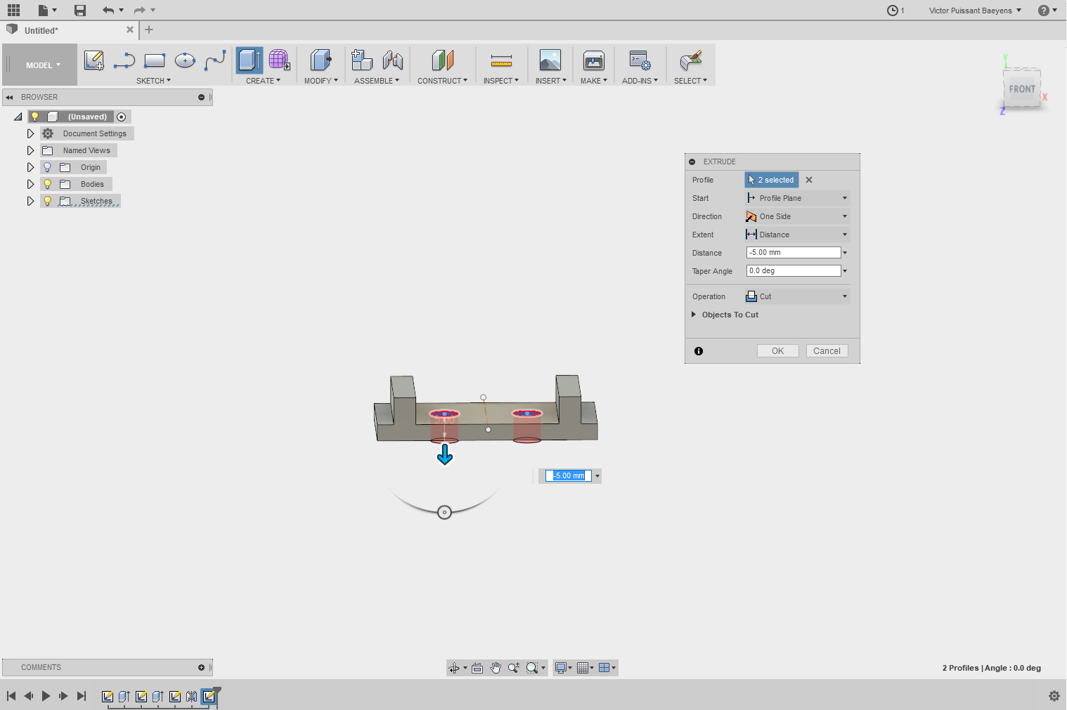
As we said, it's also available in sketch mode. So if you want to make two holes symmetrically. Just draw a circle. Draw a construction line that we'll use as our center line. Chose the distance from the center line, then select "Mirror". Select the circle as "Object" and in the "Mirror line" select the construction line
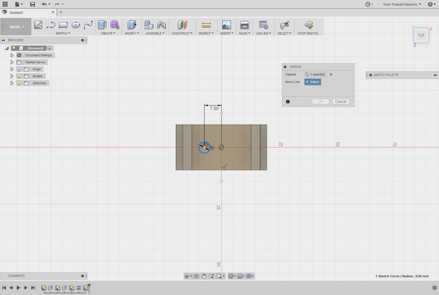
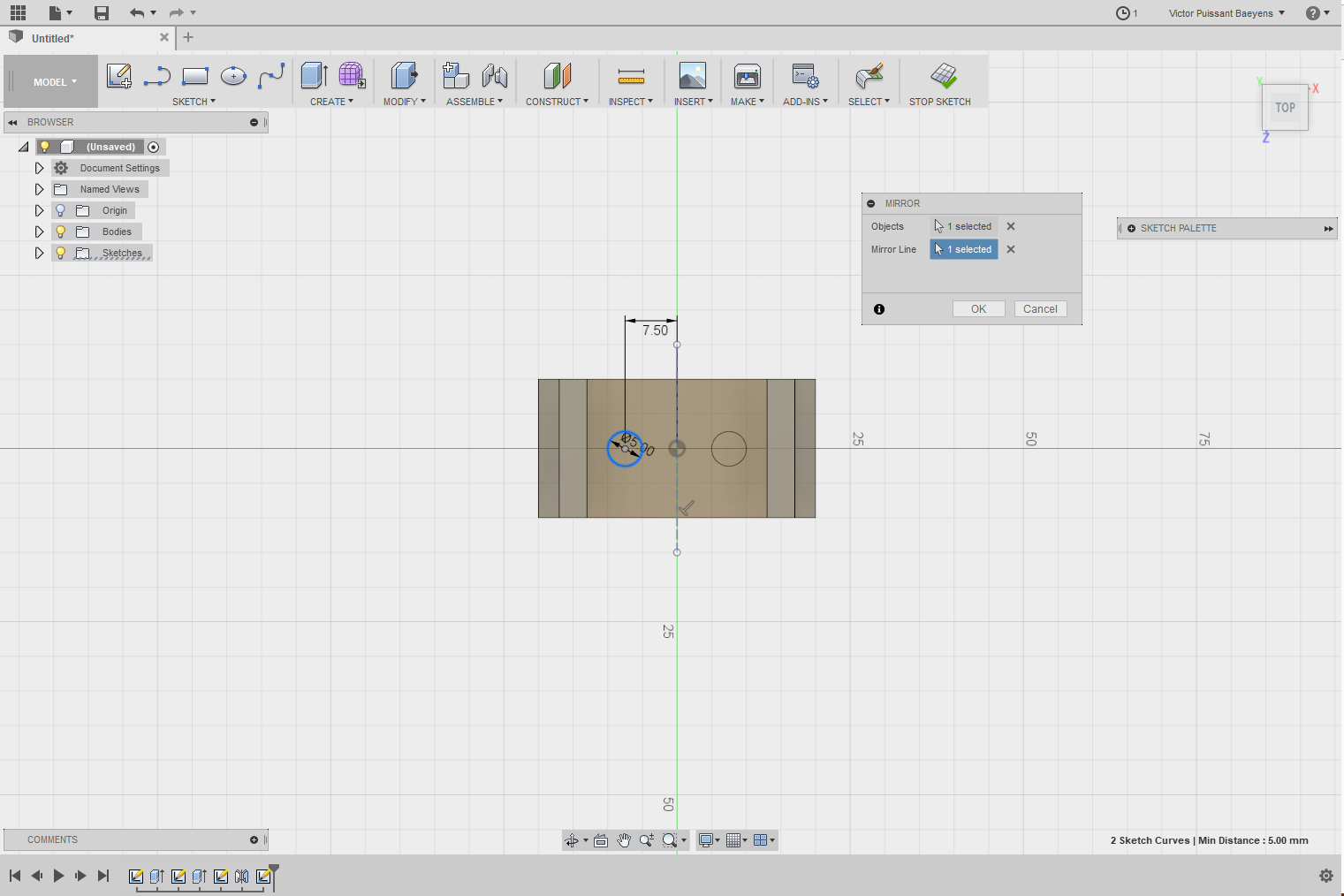
We can now make our two holes. Select the two of them (by holding "ctrl" pressed down) and then cut them through the bodie.
Fillet
As you used it in Autocad or similars, fillet allows you to joint two lines to make a curve.
In Fusion 360, as a 3D software, you'll also find the possibility to "curve" your 3D body.
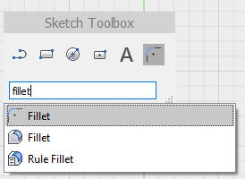
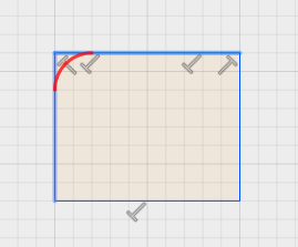
To use the sketch fillet, just select it and then click on the two lines to join.
In the 3D model, just select the edge and with the arrow or value chose the radius of your fillet.
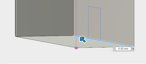
Chamfer
In the same way of thinking than for fillet, you'll have the possibility to make a chamfer.
 Select the tools and click on the edge.
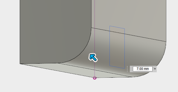
 You'll also be able to do it with a curved edge (the one made with fillet)

 Note that in this case you'll be limited by the angle of the previous made fillet.
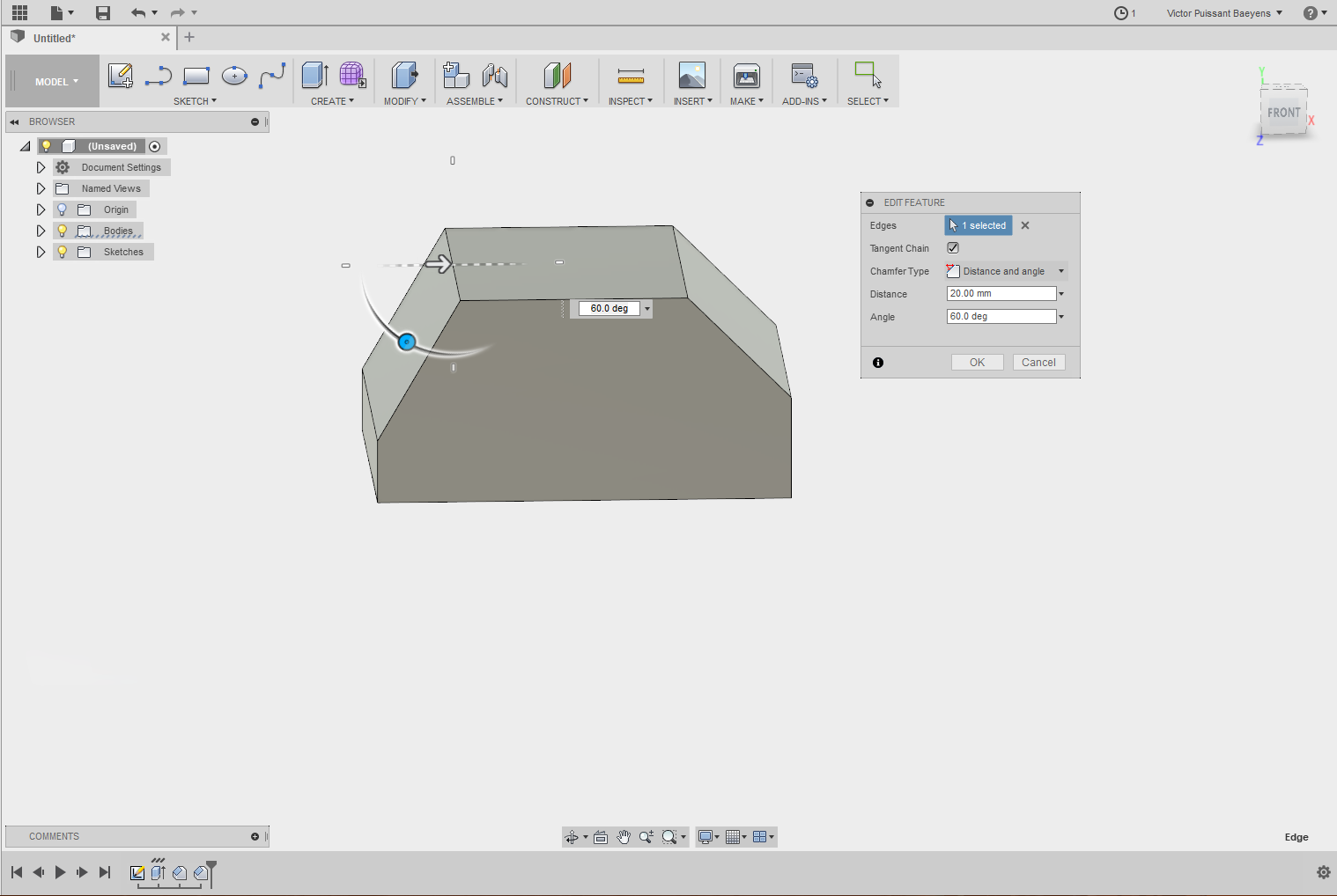
Another option is to change the "Chamfer type" and select "Distance and angle" to make a chamfer with a selected angle.
Join
A joint is a link between two pieces that describes the way they move one on the other. It comes in handy when describing actions to external people, or when modeling pieces in an assembly to avoid collisions due to design mistakes.
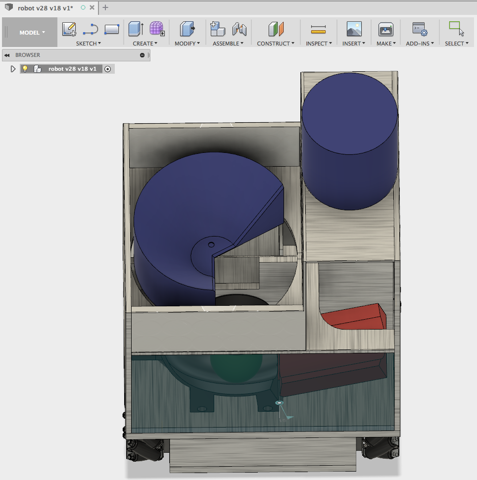
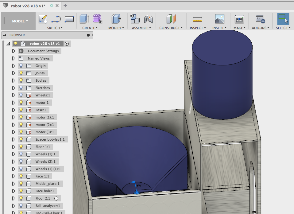
To create joints, you have to first ground components. By grounding components you avoid them to move, and so you can use them as a static reference. Take Cortex for example, the base has been grounded and all the rest around him has been jointed.
This means you can not drag it around. The second thing you have to do is create rigid groups. By searching for "rigid group" when hitting the "s" key you will enter the "rigid group" menu. You can now select all the component that should move together. You'll still be able to drag them around, but only as one group and not separately anymore. This is for example the case for the mecanum wheels as you can not move their different pieces separately.
After this is done, we can now join modules together ('j' key). To do so select the points of the modules that will touch after jointing starting with the one you want to be able to move.
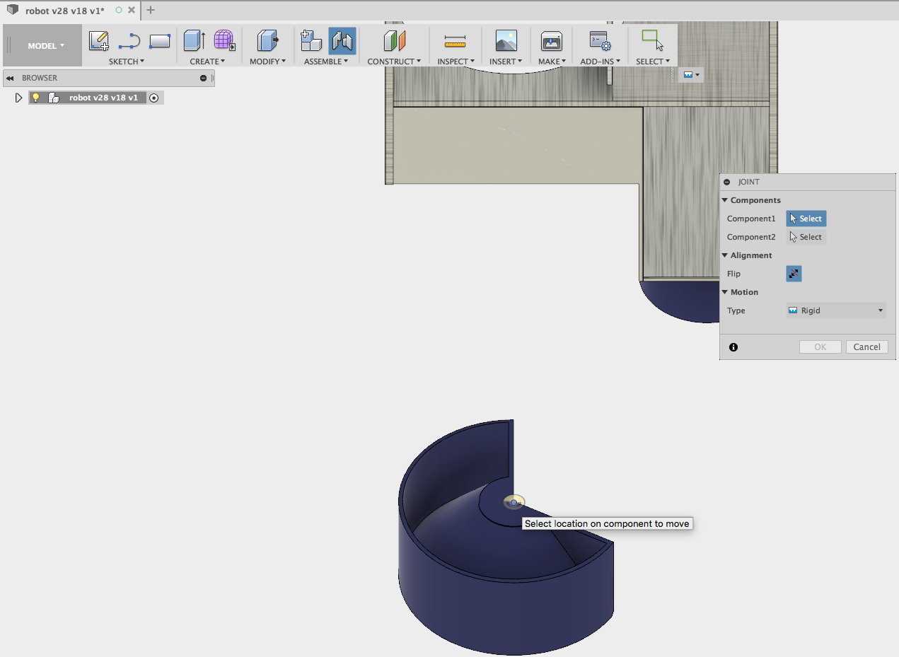
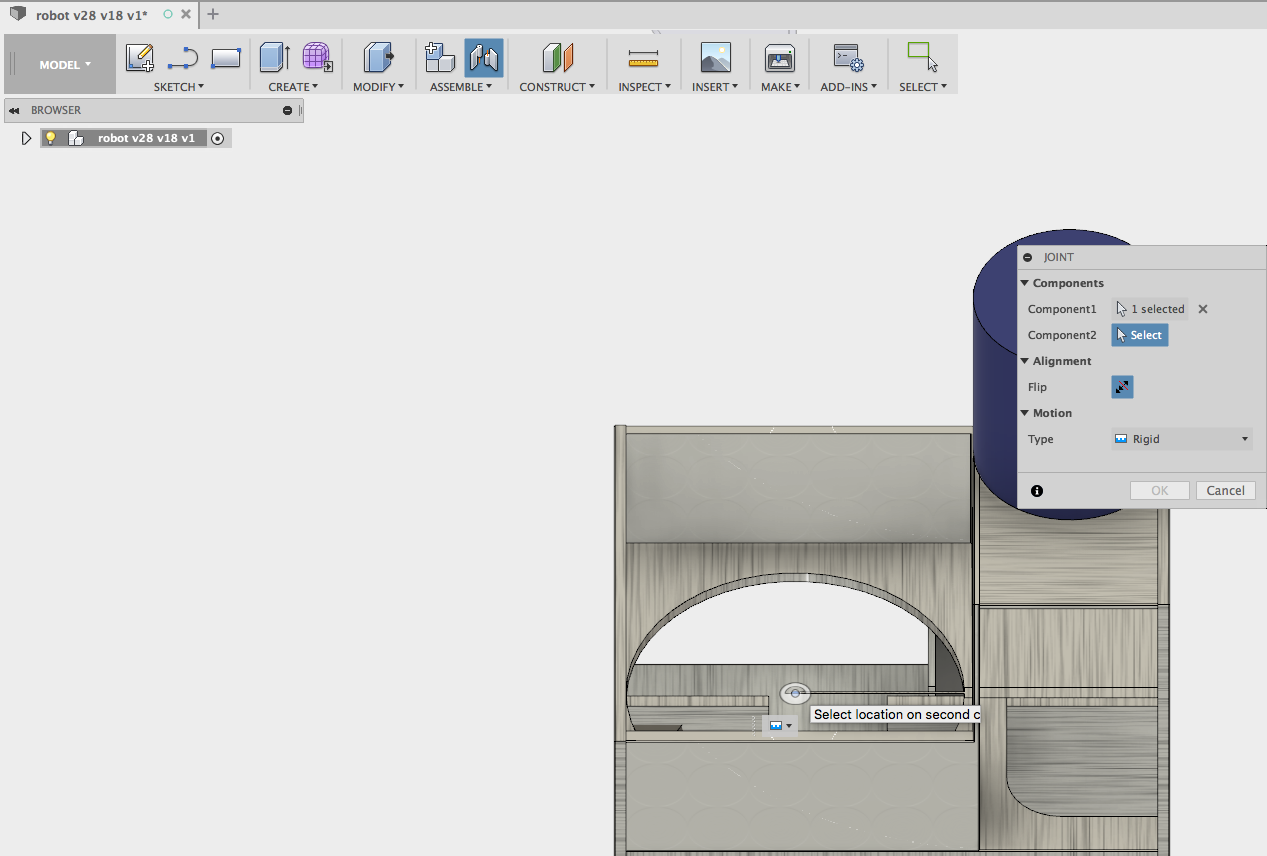
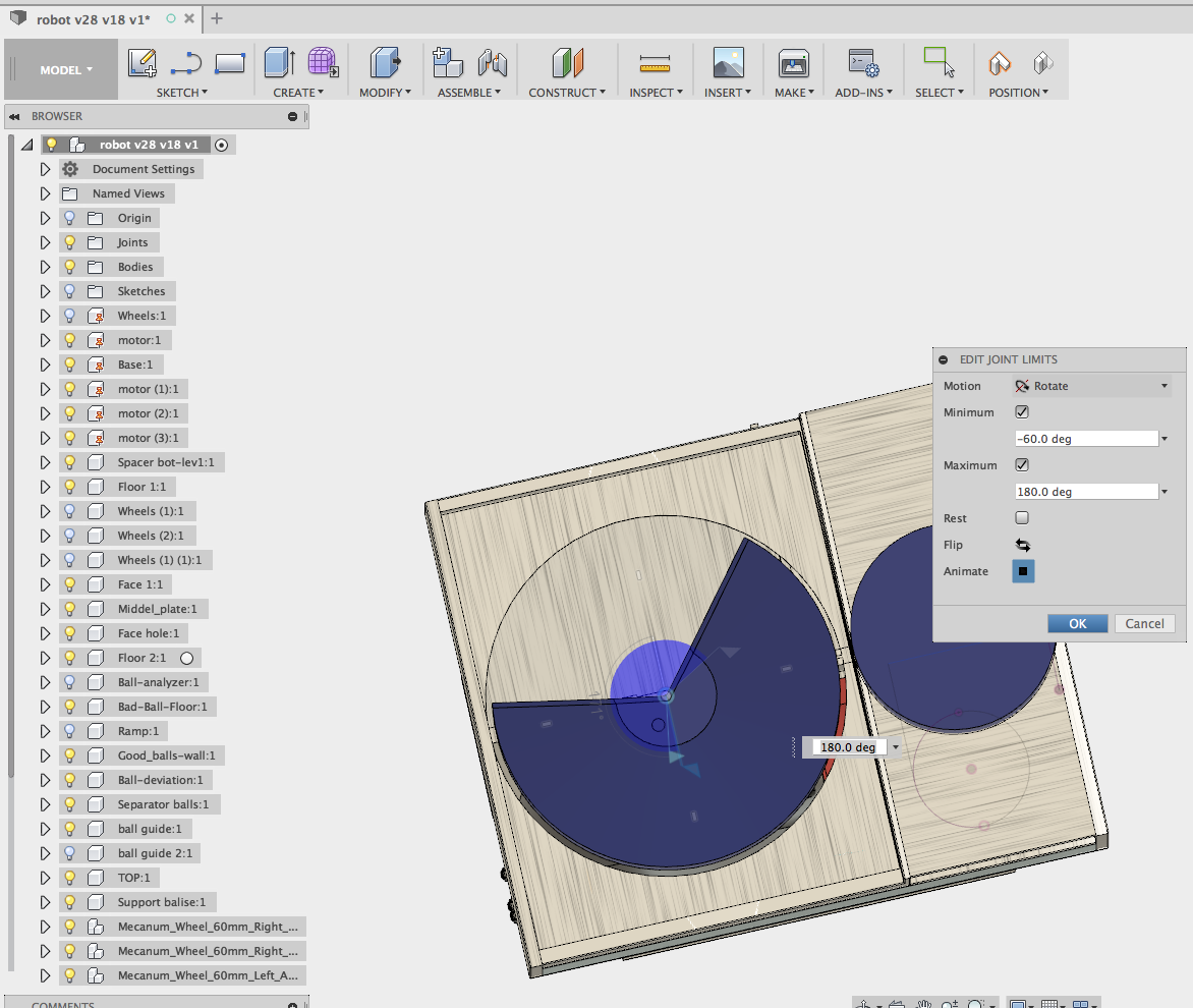
After this is done you can select the type of joint you want and the axis along which to movement will have to be.
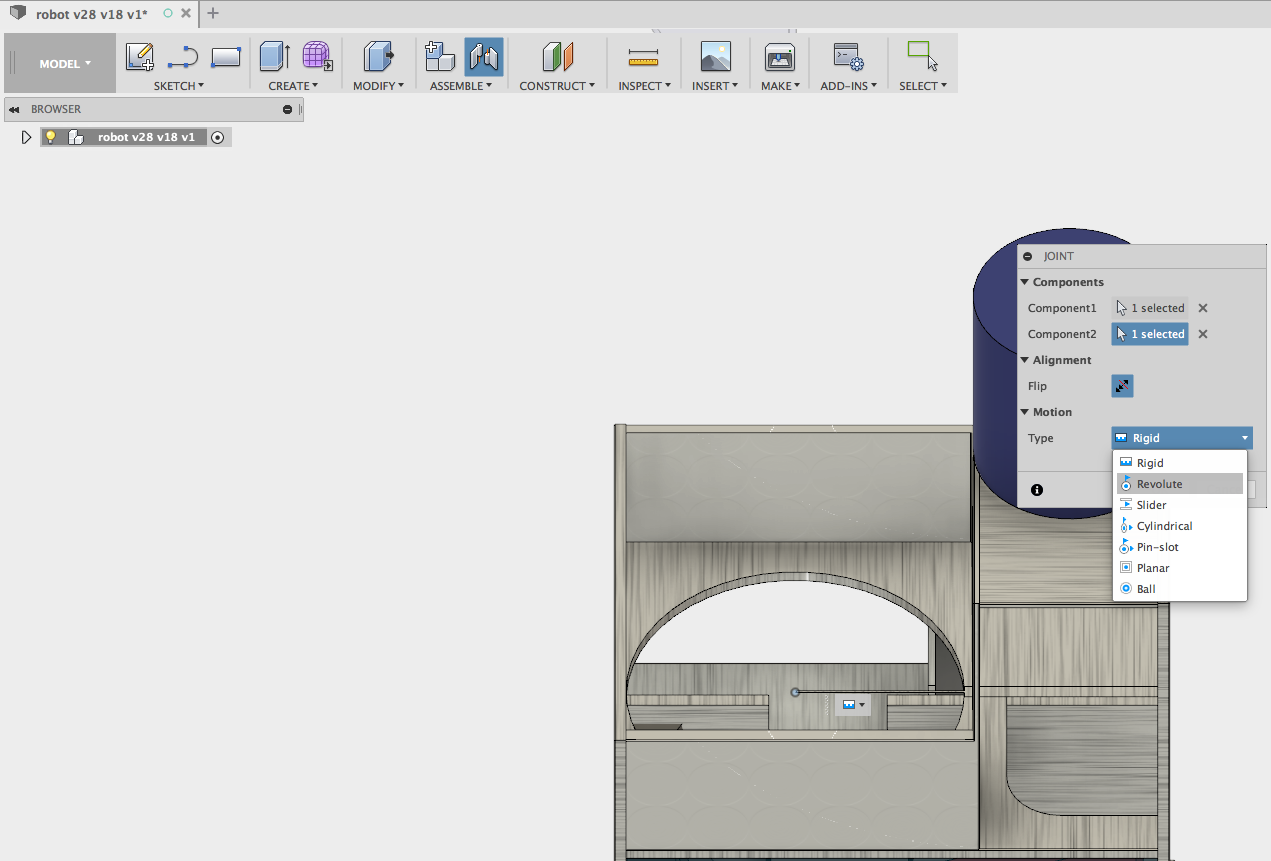
After confirming the settings, you can right-click on the joint to edit the joints limits and inverse the natural movement.
To learn more about jointing component click on the link to Lars's video about that topic Fusion 360 Tutorial — How to get a handle on Assembly and Joints in Fusion.
3. 3D Design export to plan or 3D Slicer
3.1. Design export as drawing
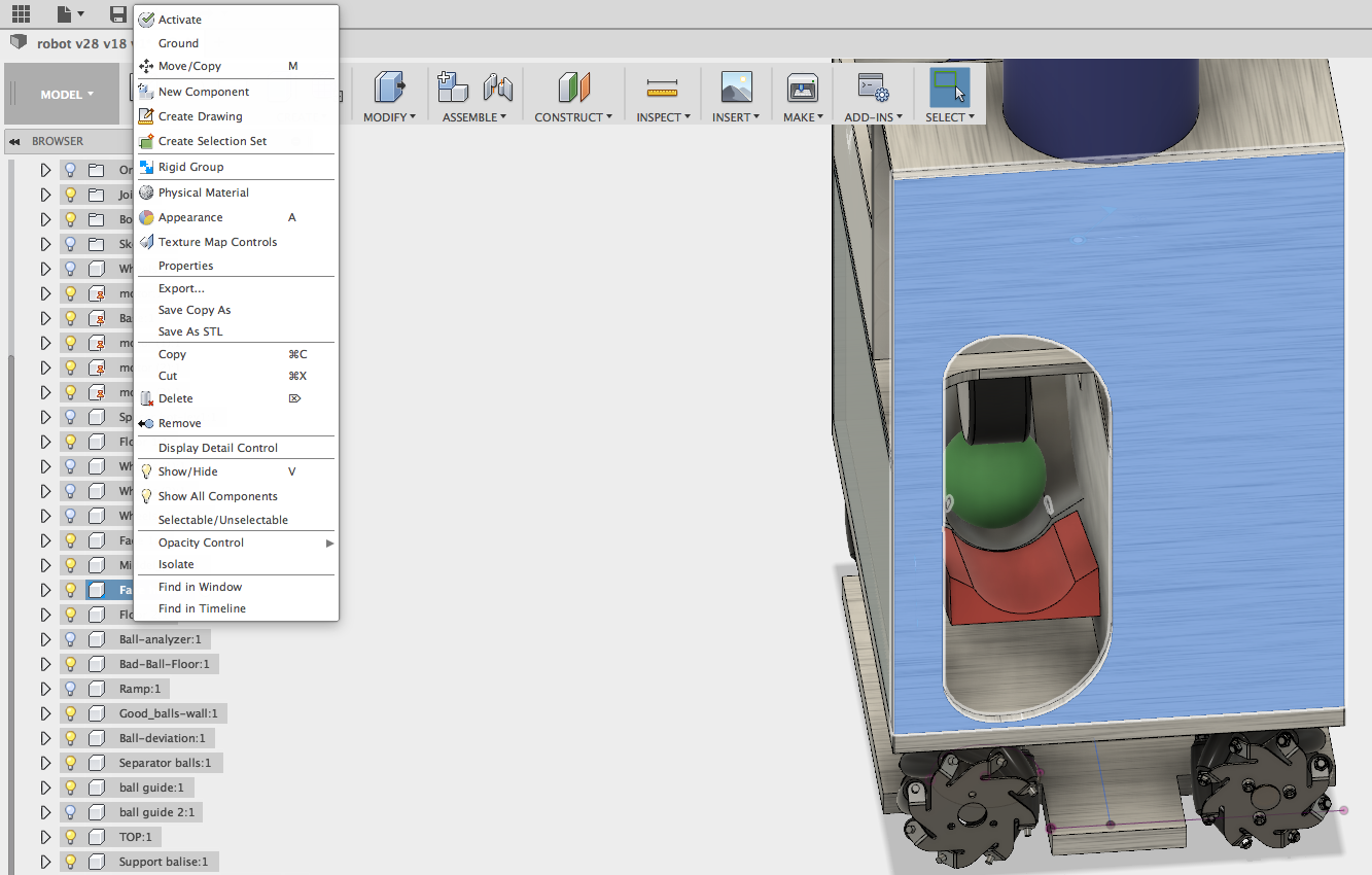
One of the main reason you have to make a 3D model before starting the actual build of your project is the ease you get to make 2D plan you can send to a manufacture or use to build the pieces your own. Making this plans will save you a lot of time and material because all the testing on designs is made virtually and not with physical materials you have to buy, cut, test, re-cut , etc... To extract the plans of the design you made, right-click on the component you want and select "create drawing".
A window pops up to specify the parts you want to include in the drawing and the format of the destination sheet (be careful on that) select the piece and click "ok".
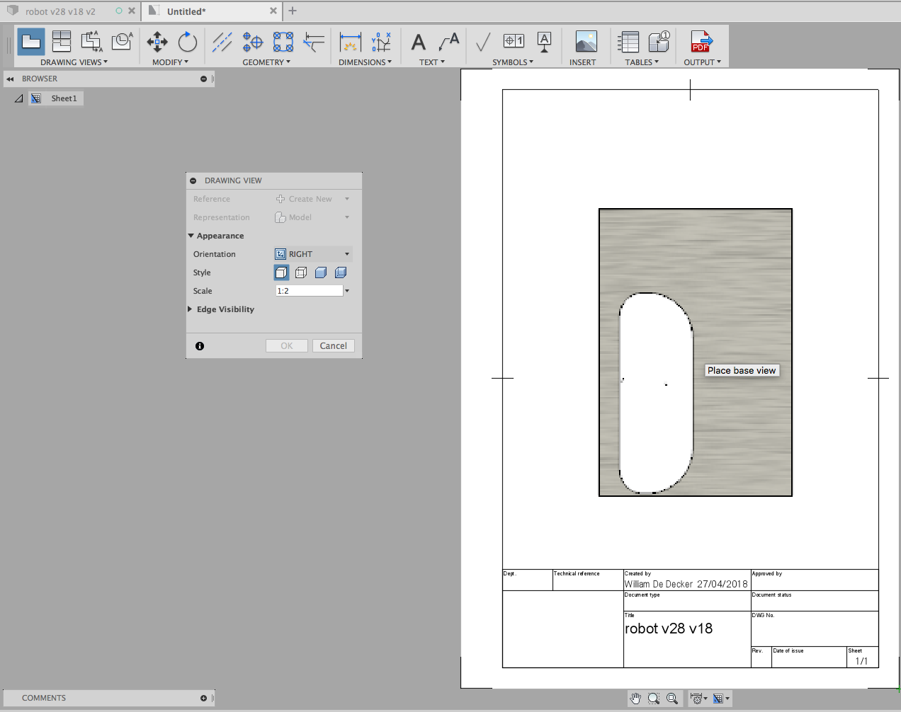
A widget is automatically created and the component is now attached to your mouse. Notice that in the small window that comes with the widget you can select the view and scale you want to use. After dropping the component and clicking "ok" on the small window your drawing is fully generated and you can start editing it.
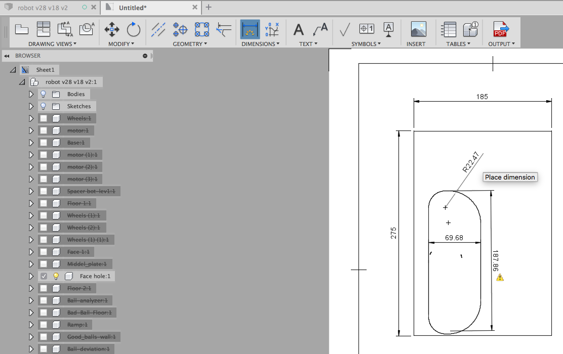
By hitting the "d" key you can start indicating the dimensions you want to specify. Save to PDF and your done.
3.2. Export 3D design (3D printing)
Now comes the fun part: 3D printing your own designs. You'll see that it is really satisfying to see something you designed your own "come to live" in the printer and to do so you will have to export you design as an '.stl' file.
First start by hitting the "make" icon in the top bar.
![]()
It will open a window asking you to select the component you want to print and where you want to send the stl file. As you might expect you have to click on the body or component you want to print (One at the time!). As most printers have an accuracy only as good as their nozzle diameter, an assembly will always be printed as one bloc! For that reason we recommend to only select bodies when printing an assembly. It takes more time to print, but if the pieces have to move their is no other way to avoid monolithic prints.
Now comes the moment you have to choose between sending your design to a facility (and generating an stl file) or printing it from your computer and send it to a slicer software (up studio for the small printer in ECAM's electronic lab, Ultimaker Cura, Repetier-host, etc...).

To create an stl file unselect "Send to 3D print utility" and select ok.
To 3D print it from your computer select "Send to 3D print utility" and link your slicer software by clicking on the folder icon. When the slicer is linked click "ok" and launch the print form your slicer that will have been open and loaded with the design by Fusion360.
4. Design import and modification
As you probably know there are tons of CAD drawings already made that can often help you in your designs. You'll find them on different formats but in general, all of them can be open with fusion or a slicer to print them.
The best known databases are:
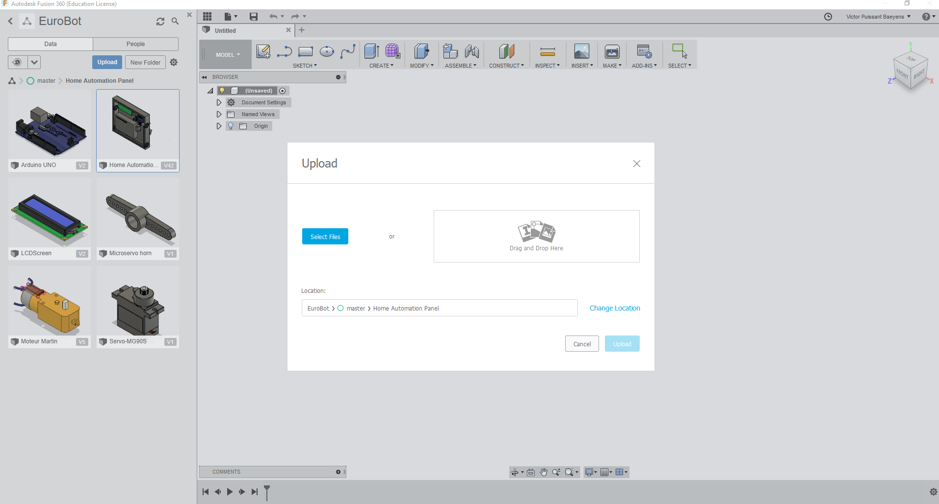
In GrabCAD, you'll find .stp, .sta, .SLDPRT files that you'll have to send into fusion to modify them and then send them in your slicer. You'll find really useful and complex design to add to yours to verify dimension and so on. We used it for example for our Home Automation Panel during the 2018 Edition, where the design of the LCD, the Arduino and the motor really helped us to fix the dimensions of the panel.
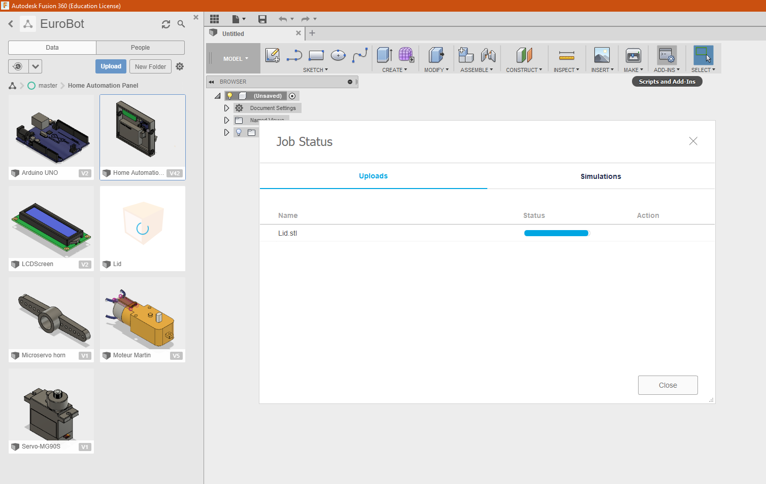
When you'll have the file that you want to implement in Fusion, just click on the upload button (top-left corner, on the project panel).
Always use this method instead of opening the file with fusion directly or it will make errors during the conversion
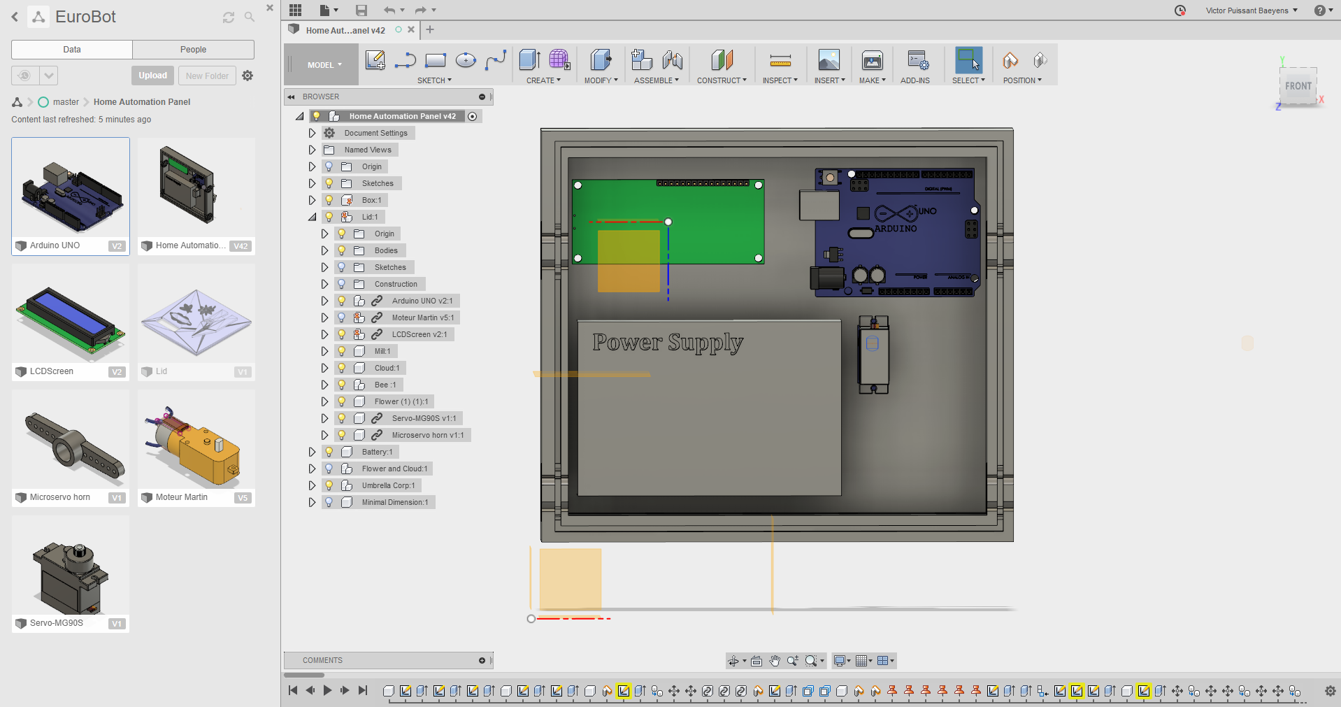
You now have the possibility to link these new designs into yours. Just open the main design to see it, right-click on the secondary design and "Insert Into Current Design". The now linked component will be shown with some chain link on it.
In Thingiverse, you'll find .stl files, already thought for the 3D printing, with some tips on how to print them sometimes.
It's also possible to modify them with the following steps.
Contributors
- Puissant Baeyens Victor, 12098, MisterTarock
- De Decker William, 14130, WilliamHdd
1. How to think 3D printing
Now that you know how to design in 3D and export your file to a slicer, we'll take you straight to the world of the 3D printing. We'll see his amazing abilities but also his limitations.
1.1. Think "mechanical properties"
When you'll have to create a mechanical piece for your robot, you have to think about the way you'll use it. For example, if it's a piece that will be in contact with water, a lot of people will have the tendency to say: "You have to use ABS!" Right now there are other possibilities as the PETG that have similar properties but has less warping. Each one of them have their advantages and their defaults. It's true that the ABS will have better mechanical resistance against wear and tear than PLA but you'll have to pay more attention at the temperature variation and the wrapping problems. That's only the top of the iceberg for the materials, if you're interested by knowing more about it, you can still find a lot on the web on divers site like: Primant3D.
Another simple tip is to think about the way the fibers during the use of the pieces.
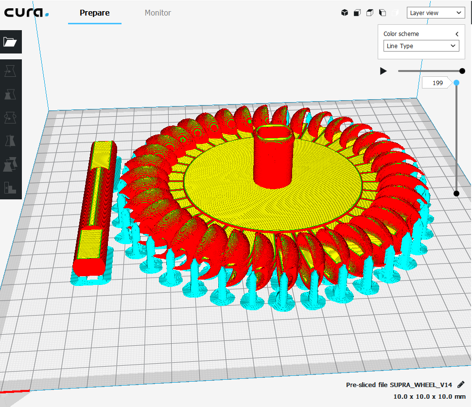
As you can see on this piece, a Pelton wheel , at first the shaft and the wheel were design as in one piece.
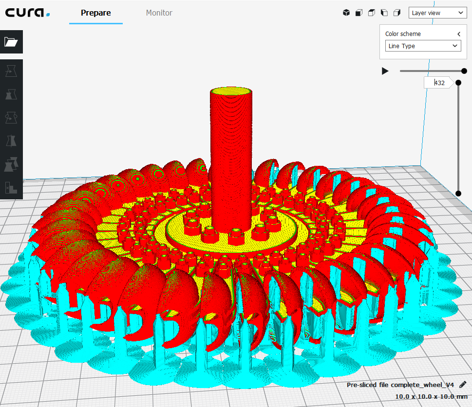
After thought, as the shaft will have to oppose strength in the radial way, it's way more efficient to print it horizontaly than verticaly (where the layers would detache).
For the wheel, it's the opposite. The spoons have to go against strength in the perpendicular way, so it had to be printed also horizontal, laying on the bed.
It was then decided to print them in two pieces.
1.2. Think about the supports
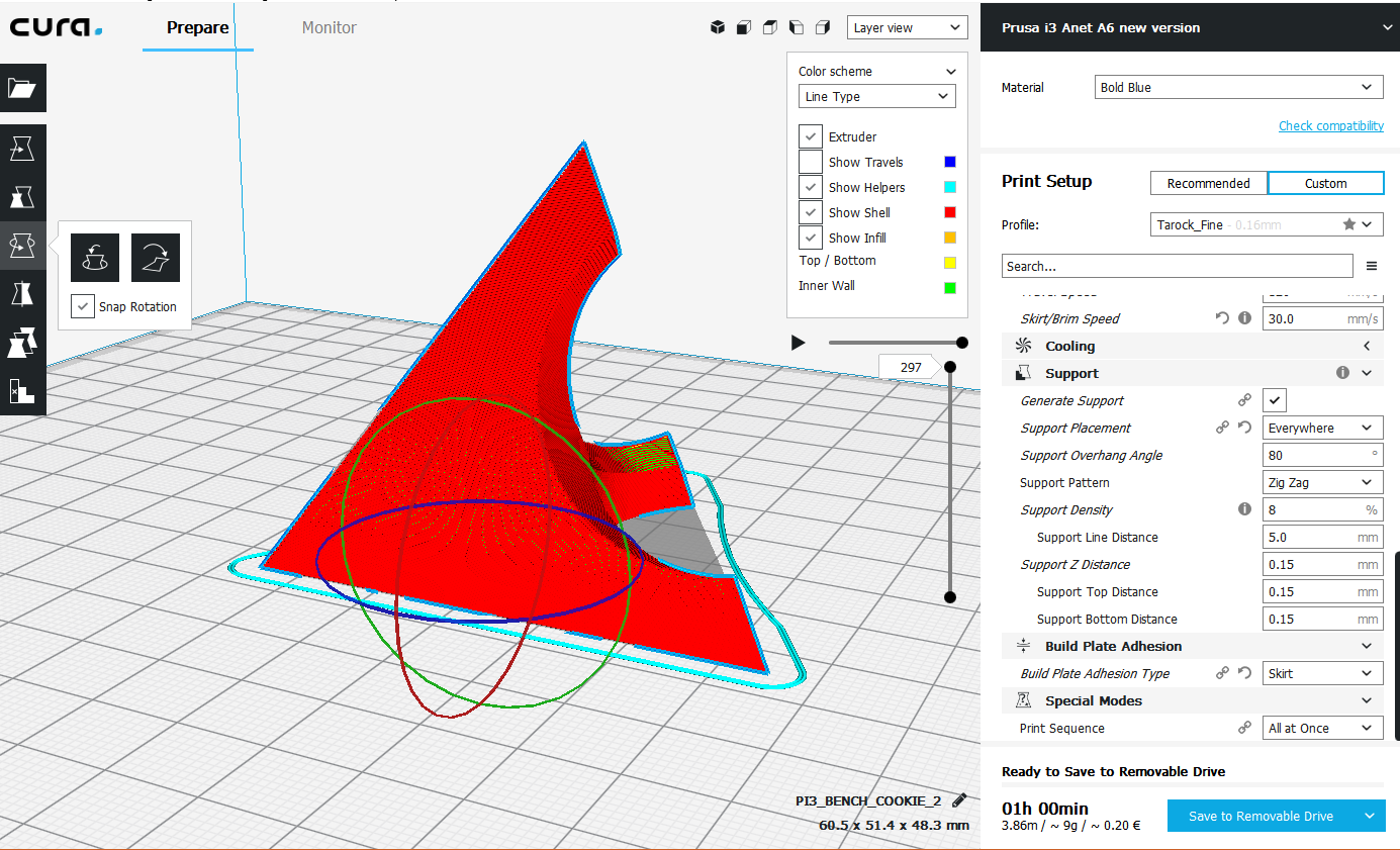
As you'll see in the point 3. Printer Configuration, there are a lot of different parameters to take into account. In this point, we'll speak about the supports, their necessity and their troubles.
As you can see on the picture below, there a lots of support placed to help the printer. As the print is done layer by layer, it needs supports to help the extrusion of part on empty space.
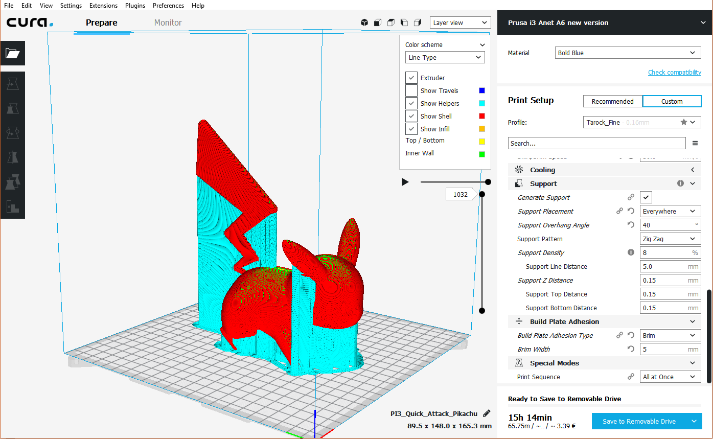 Note that you'll have to be in layer view to see them (Top-Right Corner)
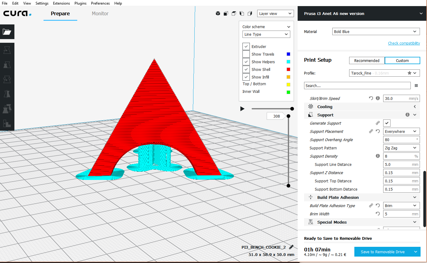
The most used to tune your print is the Overhang Angle, it will allow you to control the amount and place of the supports.
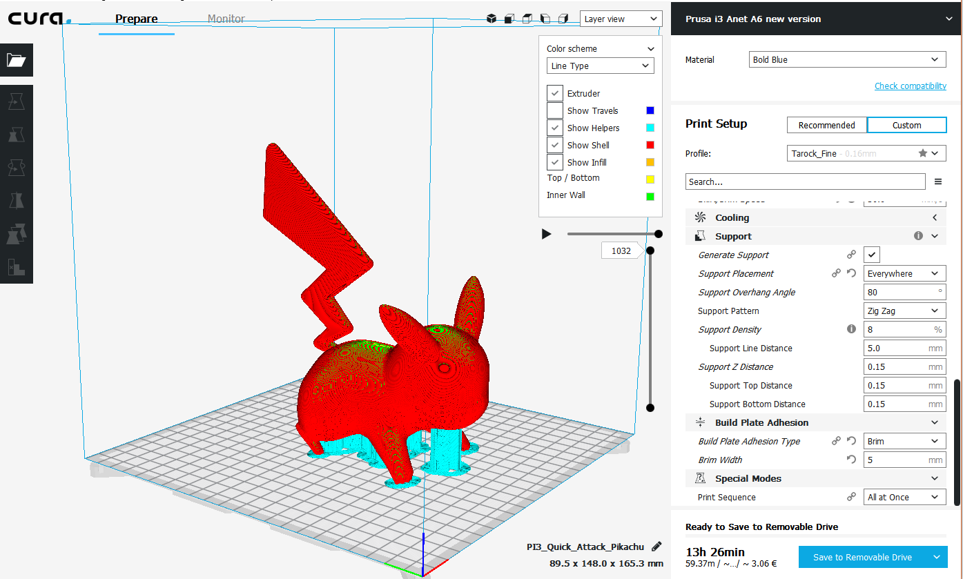
The use of limiting the amount of support is to reduce waste, reduce printing time (in this case 1h45) but also cleaning time as you'll have to cut or tear them apart by hand. There is a possibility with dual extrusion to print them with PVA (water soluble filament) but it requires a more expensive printer.
However, I recommend to try the parameters shown on the picture because they make the removing of supports way easier than the default one.
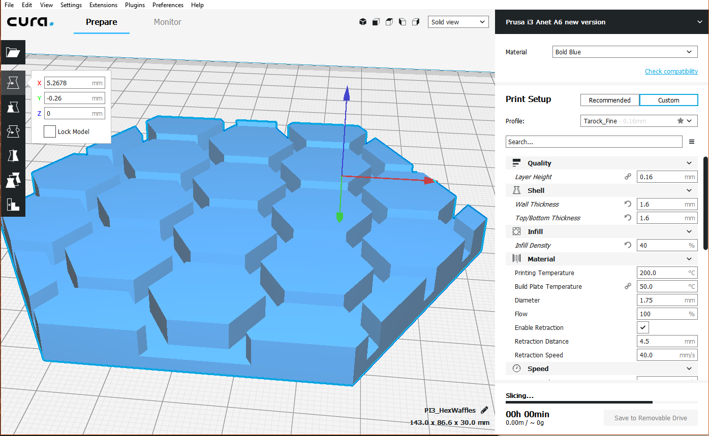
1.3. Think about the face laying on the heat bed
As said before, the printer will often need support, but the orientation of the piece on the bed will also help a lot to reduce them.
In this piece, simply by laying it on one face, you'll remove all the need for support.
In this case, it would be absurd to put it on the other face as it will require a lot of support and their will be very complex to remove.
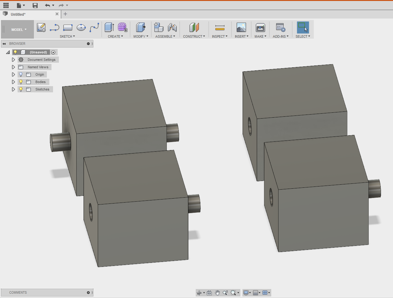
On this final picture, imagine many of this cubes needing to be plugged one in another and that have to be printed on their left face. You can use two different design:
- In the first design (the two top cube) the top-left one will require support.
- In the second design (the two cube below) the low-left one can be printed easily.
More, in the second design, all the cube are the same so you can print a lot of them really fast.
2. What printer to choose?
The offer in mater of 3D printers is enormous and can be confusing to an unexperimented printer. And even if you know what you are looking for, you can find the same looking printer for at least 10 different prices and brands. As a matter of fact a lot of companies copy the "big ones" and sale these copies a lot cheaper. These copies can be a very good investment for non-professional work and can save you quite a few euros, but can also be a real nightmare.
A general advice is to read as many reviews as possible and to try to choses a printer that a lot of people have. Isolated brands are often isolated for a very good reason (quality issues for example) and you'll struggle finding informations on settings, performances and things like parts to print to upgrade you printer.
The Anet company for example is very popular brand that sells versions of open source printers. The are close to the cheapest you can find, but have very decent quality and high liability. Hereby lots of people have one and you can find tones of parts on Thingiverse AnetA8 to upgrade their models.
Other companies like FLSUN sale some of the same open source models (prusa i3) a like more expensive but are less reliable and upgrade parts are pretty difficult to find.
So what to chose ?
Well we are not going to give you a list of printers to buy or not to buy, but we'll try to give you guidelines to follow when comparing what the market offers.
2.1. Technologies
Men have developed different ways to 3D print stuff, each and every one of it with its own advantages. The cheapest and thus most used is the extrusion of molten plastic, but others like resin printing (where a laser hits a bath of liquid resin hardening it instantly) or metal printing (same idea as for resin but with a bath of metal powder), are starting to emerge. These however are really expensive (2 000$ up to hundreds of thousands of dollars for the machine only) for the moment and won't be discussed any further.
The rest of this document will so only speak about plastic extrusion printing.
2.2. Structure of the printer
You'll find two main types of structures: cartesian and delta.
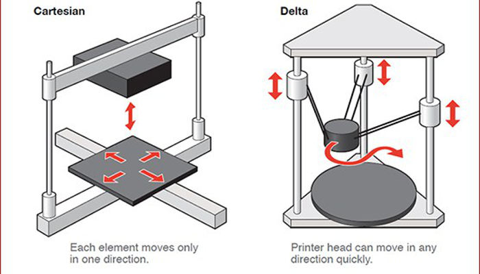
Delta 3D printers were designed for speed, but they also have the distinction to have a print bed that never moves, which may come in handy for certain print jobs. In the other hand, their speed comes with a certain weakness for details and a lack in precision.
Cartesian printers are better for details and easier to build and maintain, but slower.
2.3. Precision
As you might expect, cheap printers (100€-400€) don't have the same accuracy as semi-professional ones that cost about 2000€-5000€ (Ultimakers for example). This can be scaring at first, but think about it this way: do you really need to print at a resolution of 20 microns (an aluminum sheet is about 16 microns )? For most of the prints you'll make a precision of 0,2mm and a little bit of sanding is more than enough. You can find more than decent printers for around 200€ (Anet A6) for medium bed sizes. Larger bed printers will cost about 300€ (Creality3D CR - 10). Note that these printers are DIY printers so you'll have to assemble them your own. This might take a few days, but is a piece of cake with the manual and will save you a few hundred euros.
2.4. Links
To close the subject, here are some links you could find handy in your search of a 3Dprinter to acquire or to improve.
- Thingiverse AnetA8
- Instructables improvement
- Choose between a Bowden or Direct extruder
- Anet A8 vs A6
- Anet A8 improvement
3. Printer Configuration
There are tons of different parameters that will influence the quality of your print. It would be out of the topic to list them all but we encourage you to read the following document to calibrate your printer as good as possible.
4. Some tips before printing
The Ultimaker 2+ is the printer that we are using for our 3D model. Before using the printer, there are some points to check :
- The filament
- Is it a PLA ?
- Is it a 2.85 mm width ?
- Isn’t it stuck ?
- Is it in the right position?
- The build plate
- Placement, adjust it accordingly (follow the instructions on the printer)
- They may have some adherence issues, the trick is to use glue on the plate
When you lunch the printing, always wait for the 1 layer before leaving, it may have some adjustment error or filament can be stuck.
Troubleshooting
If the filament is stuck, it doesn't come out, stop the printing.
It may happen because :
- The filament is stuck and it can't feed the printer
- The nozzle is clogged
If the nozzle is clogged try the Atomic solution
Else try https://ultimaker.com/en/resources/11704-extrusion-problems
Contributors
- Puissant Baeyens Victor, 12098, MisterTarock
- De Decker William, 14130, WilliamHdd
- Ping Tian-sen 16333
Rules of good use of 360° merger
Make files for each part of the robot. Explicitly name the name of each folder If necessary, create a folder for electronic components, tags,.....
Make each part of each part independently to have a faster modification later on.
Give an explicit name for each part in order to be readable by everyone who would like to consult the hub. Try to keep the same name of every same parts, like right panel, right side,…
Make an assembly with all the parts drawn and make an overall drawing. Do not forget to create rigid groups and joints to make it easier to place the parts. The advantage is that when we modify a part included in the set, the assembly will be updated with the new dimensions of the part.
Assemble all the assemblies to finish the robot drawings. Once again, the assemblies will be updated as they are modified
Mecanum wheels
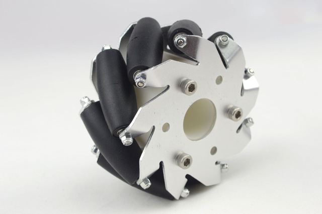
A mecanum wheel is a wheel with rollers attached at its circumference at an angle of typically 45°. When four mecanum wheels are used together, we can achieve a net resulting direction in any direction by varying the direction and speed of rotation of the wheels.
Assembly
Wheel adapter
To mount the wheels onto the motors, we need to use an adapter. Due to an error in our order, we didn't receive the correct adapters and the ones we received didn't fit on the wheels.
We decided to 3D print our own as a replacement. The STL file for this part can be found here.
Note:
3D printing parts that will be under moderate or heavy mechanical stress is often not the best idea, because those parts will tend to break and/or wear out quickly.
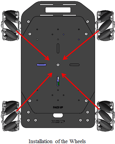
Wheel orientation
When assembling the wheels onto the robot, we need to pay attention to their orientation. If we look from the top view, the rollers should all point to the center of the base.
Kinematics
Forward kinematics refers to the use of the kinematic equations of a robot to compute the position of the end-effector from specified values for the joint parameters. In our case, the forward kinematics allow us to compute the global velocity of the robots base when given the angular velocities of the individual wheels.
The reverse process that computes the joint parameters that achieve a specified position of the end-effector is known as inverse kinematics. The inverse kinematic equations allow us, in our case, to compute the individual wheel velocities needed to achieve a given base velocity.
The equations presented in the next sections come from the following research paper: "Kinematic Model of a Four Mecanum Wheeled Mobile Robot"
Inverse kinematics
The inverse kinematic equations allow us to compute the indiviual wheel velocities when we want to achieve an overall base velocity.
- \(\omega_{fl}\), \(\omega_{fr}\), \(\omega_{rl}\) and \(\omega_{rr}\) represent the angular velocities for the front left, front right, rear left and rear right wheel respectively.
- \(v_x\) and \(v_y\) represent the robot's base linear velocity in the x and y direction respectively. The x direction is in front of the robot.
- \(\omega_z\) is angular velocity of the robot's base around the z-axis.
- \(l_x\) and \(l_y\) represent the distance from the robot's center to the wheels projected on the x and y axis respectively.
Or in matrix form:
\[ \begin{bmatrix} \omega_{fl} \\ \omega_{fr}\\ \omega_{rl}\\ \omega_{rr} \end{bmatrix} = \frac{1}{r} \begin{bmatrix} 1 & -1 & -(l_x + l_y) \\ 1 & 1 & (l_x + l_y) \\ 1 & 1 & -(l_x + l_y) \\ 1 & -1 & (l_x + l_y) \end{bmatrix} \begin{bmatrix} v_x\\ v_y\\ \omega_z \end{bmatrix} \]Example
If we want to let the robot move diagonally at 0.22 m/s in the x direction and 0.11 m/s in the y direction. At what speed should we set the motors of each wheel?
The robot is 15 cm in width and 20 cm in length. The wheels are placed at the extremities and have a diameter of 60 mm.
\[ \left\{\begin{matrix} \omega_{fl} &= \frac{1}{0.03} \left[0.22 - 0.11 - (0.2 + 0.15) \cdot 0 \right ] = 3.66 \; rad / s\\ \omega_{fr} &= \frac{1}{0.03} \left[0.22 + 0.11 + (0.2 + 0.15) \cdot 0 \right ] = 11 \; rad / s \\ \omega_{rl} &= \frac{1}{0.03} \left[0.22 + 0.11 - (0.2 + 0.15) \cdot 0 \right ] = 11 \; rad/s \\ \omega_{rr} &= \frac{1}{0.03} \left[0.22 - 0.11 + (0.2 + 0.15) \cdot 0 \right ] = 3.66 \; rad/s \end{matrix}\right. \]
Forward kinematics
The forward kinematic equations allow us to compute the robot's base velocity when given the individual wheel velocities. This is usefull to compute the robot's odometry using the motor's embedded quadrature encoders.
Odometry is the use of sensor data to estimate the change in position of the robot over time.
\[ \left\{\begin{matrix} v_x & = (\omega_{fl} + \omega_{fr} + \omega_{rl} + \omega_{rr}) \cdot \frac{r}{4}\\ v_y & = (-\omega_{fl} + \omega_{fr} + \omega_{rl} - \omega_{rr}) \cdot \frac{r}{4}\\ \omega_z & = (-\omega_{fl} + \omega_{fr} - \omega_{rl} + \omega_{rr}) \cdot \frac{r}{4(l_x + l_y)} \end{matrix}\right. \]Or in matrix form:
\[ \begin{bmatrix} v_x\\ v_y\\ \omega_z \end{bmatrix} = \frac{r}{4} \begin{bmatrix} 1 & 1 & 1 & 1\\ -1 & 1 & 1 & -1\\ -\frac{1}{(l_x+l_y)} & \frac{1}{(l_x+l_y)} & -\frac{1}{(l_x+l_y)} & \frac{1}{(l_x+l_y)} \end{bmatrix} \begin{bmatrix} \omega_{fl}\\ \omega_{fr}\\ \omega_{rl}\\ \omega_{rr} \end{bmatrix} \]Code
For an implementation of the mecanum wheels in the code, refer to chapter: Mecanum wheels in software
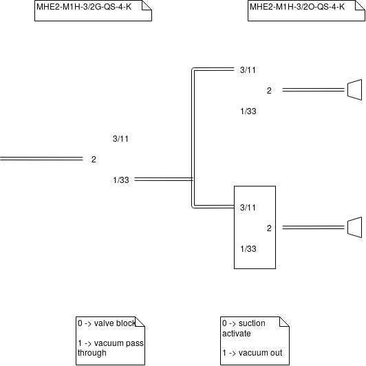
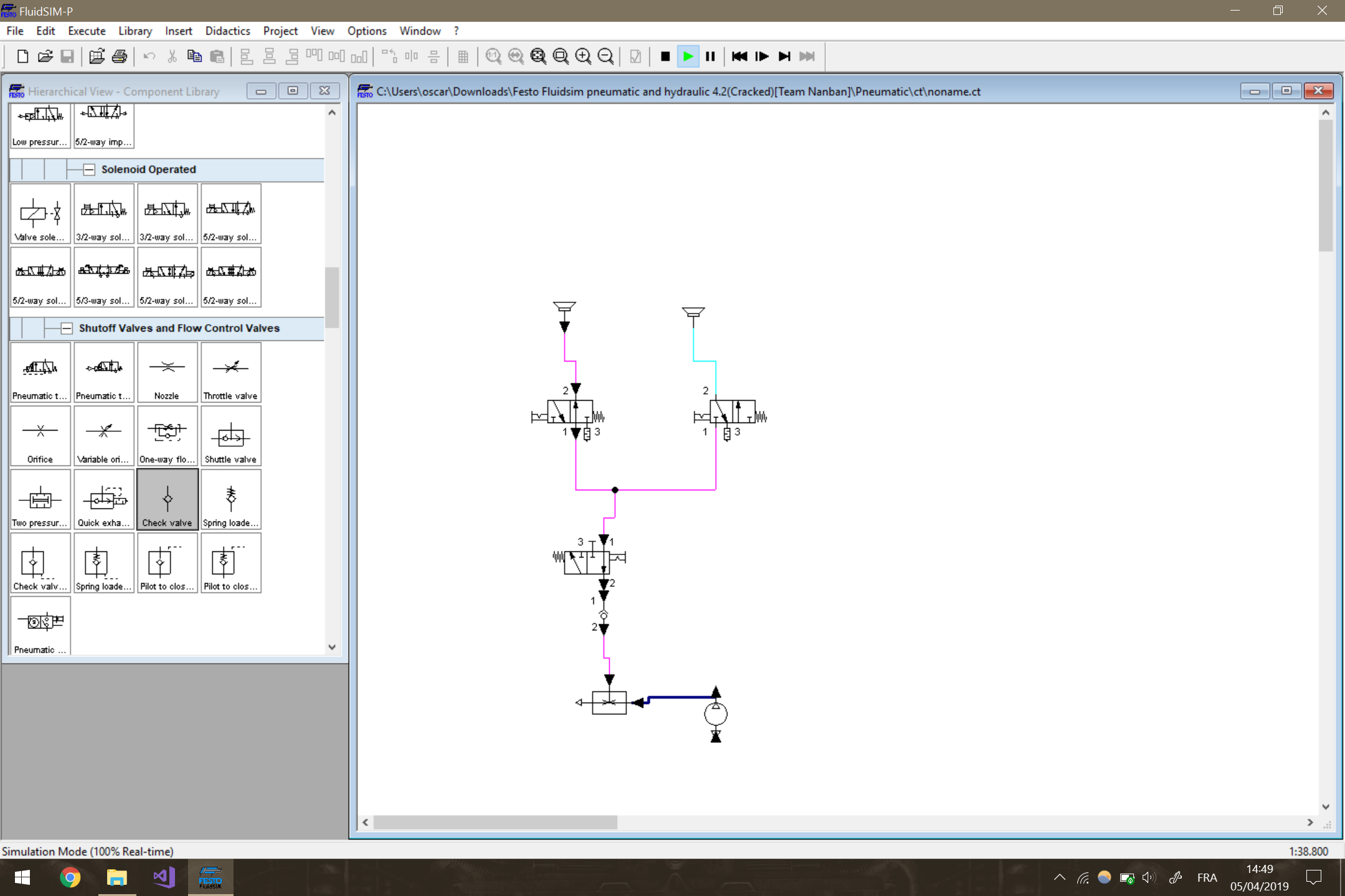
Vacuum prehention
To take the pucks, we use a vacuum system.
The material list:
- pump
- valve
- suction cup
The material is from Festo (we can have good price for student projetcs)
Other prehention systems were use to take the pucks of the 2019 contests: like shovel.
Pros
- mechanism is easy to take flat surface
Cons
- the pump use lot of power
- the pump and the valve take lot of space
2018 Specifics
In 2018, the two big mechanical tasks were:
- Collect cubes that are distributed at specific locations on the playing field. The collected blocks then need to be stacked to create a tower. For each story (level), a bigger amount of points were given. Additionally, if the tower contained the 3 cube séquence, revealed at the beginning of the match, additionnal points were earned.
- Collect foam ping-pong balls from the dispensers. The robot first has to open the lock so that the balls can fall out of the dispenser. Then the robot had to sort the balls and, depending on their color, either shoot them into a "tower" or put them in another recipient.
The big robot specifications
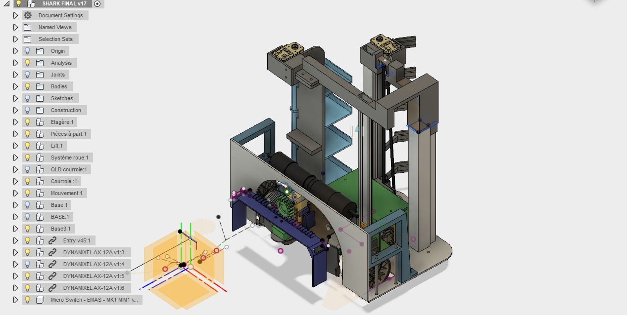
Fusion 360
The entire robot is designed in Fusion 360 and is available on the Eurobot cloud. The final version is called SHARK FINAL V17
Here is the link to download de fusion projet : BigRobotModel
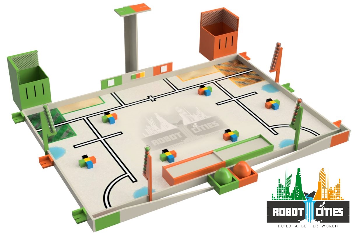
The goal of the 2018 edition
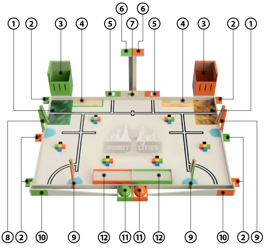
The robot starts from the inital surface (number 1).
The robot has to collect the cubes and to build a tower of 5 cubes maximum in the construction zone (number 4). The team earns a lot a point if it respects the construction plan shown on the wall (number 7).
Sections ( How does it work ?)
This paragraph explains the differents conceptions's steps and all the parts needed to build a tower. Here is the general flow diagram :
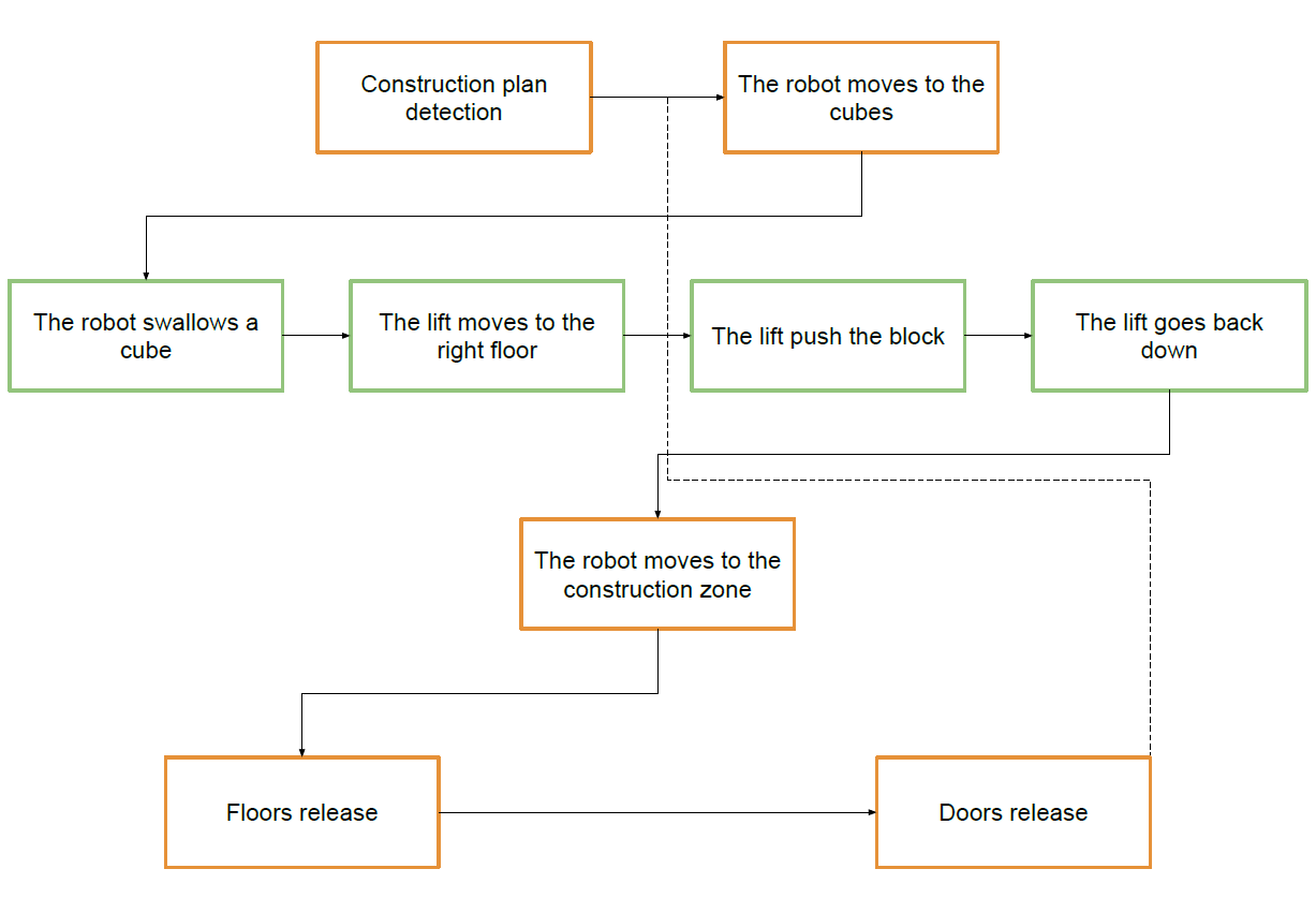
The system doesn't need any color detection because all the stars of cubes are always in the same order in the same direction.
The base
This is the firt thing I'm going to talk about but it was the last designed part. Indeed, every part had to be designed to know the constraints and dimensions. Thoses informations where essentials to design the base.
After the design in Fusion 360 in the model environment, the design was imported to the CAM environment still in Fusion.
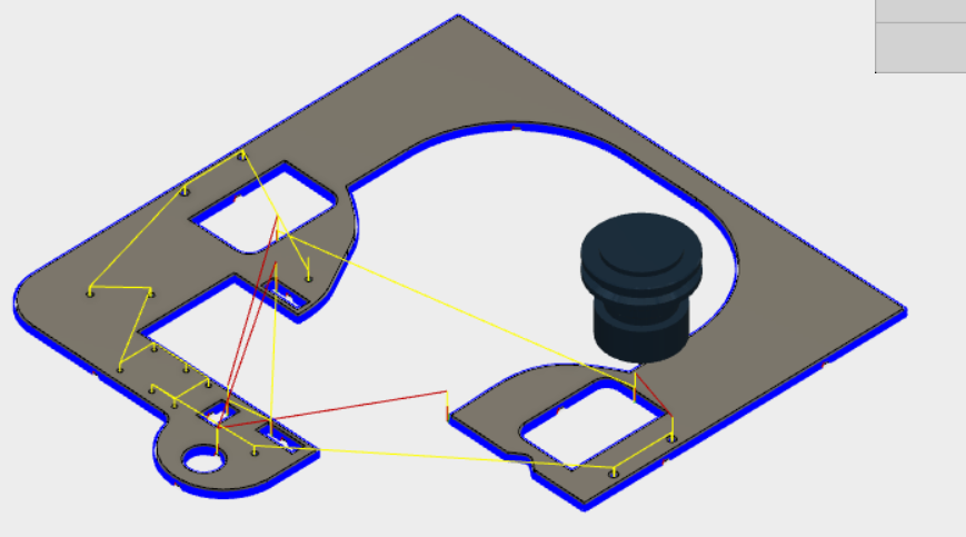
It was then machined with a CNC :

The entry
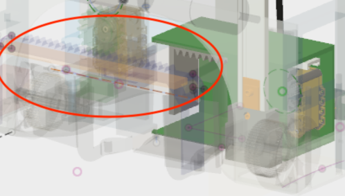
To swallow the cubes, an entry was designed. It uses simple DC motor with paint roller bought at the Brico.
The entry swallows the first 3 cubes and then select the fourth cube between the 2 last by pushing it with the toothed rack. After that the robot do the same step with the last cube. The rack moves with a rail available on RS component :
IGUS rail:
- Rail :Igus N Series, NS-01-17-300, Linear Guide Rail 17mm width 300mm length
- Carriage : Igus Linear Guide Carriage NW-02-17, N
To detect when the cube is in the lift, the robot uses a limit switch available on RS Component :
Limit switch : Snap Action Limit Switch, Roller Lever, Thermoplastic, NC, 125V.
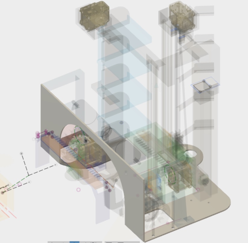
The lift
The limit switch used in the entry is connected to a pin of an Arduino Uno board so we can detect the state change when a block touches the switch. That event triggers the lift and thus the block starts to raise up. Therefore we are using another DC motor with a belt as you can see on the picture below.
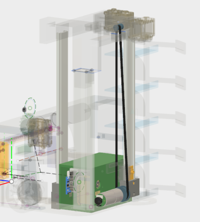
Thanks to the colour detection we know in which order we have to collect the blocks on the field, so we also know which one comes first in the lift and which floor it has to go to. It is important to know the specific floor in order to create the pattern showed at the beginning of the game and recognised by the colour and sequence recognition part.
To know when the lift has to stop, we use the encoder of the DC motor so we can precisely know when the motor has to stop. The encoder is connected to an interruption pin on the Arduino board so the tick counts can be more accurate and have priority.
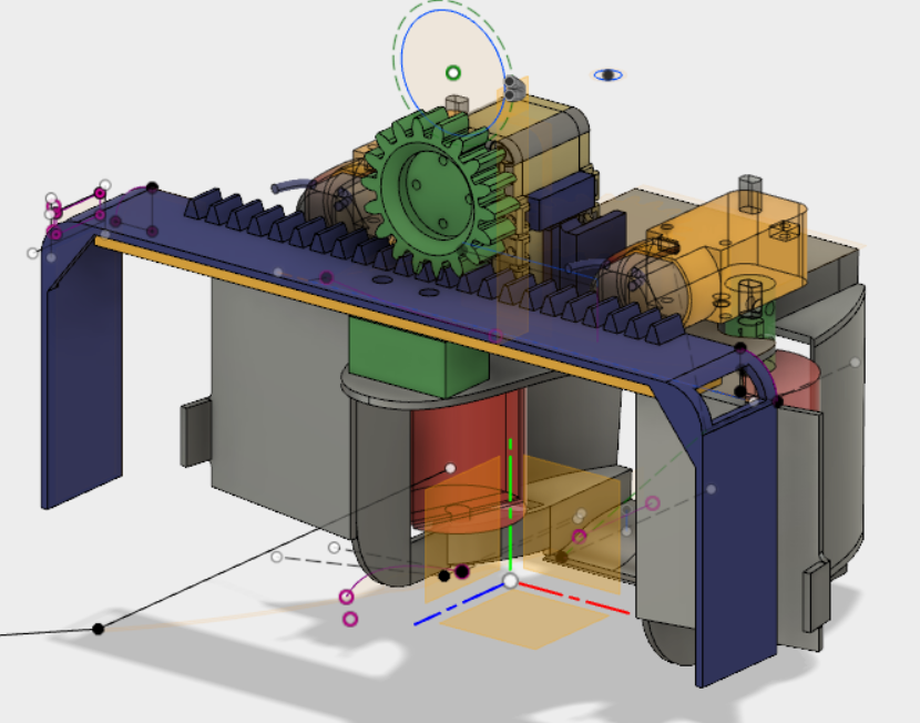
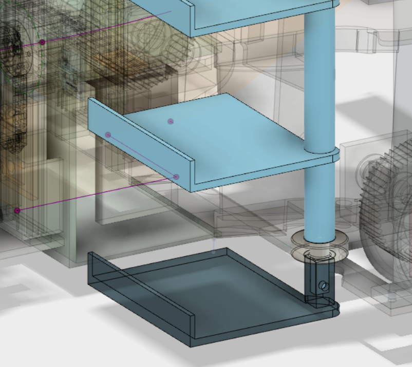
Once the block is on the right floor, it has to be pushed outside of the lift to already be placed in its position on the tower on a kind of shelf (as you can see in the picture below) which supports the blocks even if there is no other block below.
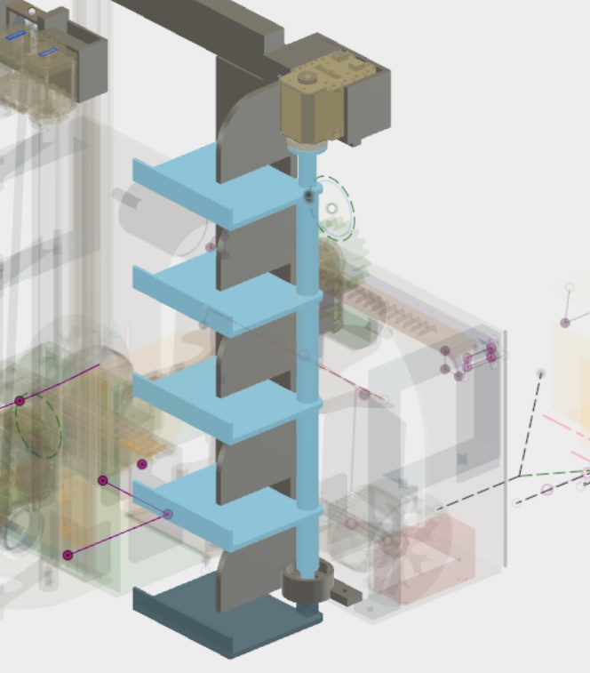
Furthermore, to push the block, we use a dynamixel with a gear and a tooth rack to slide a plate along which pushes the block until it reaches the « shelf ».
Then the lift (without any block inside) goes down. To make sure it doesn’t go too much we use another limit switch. Therefore the lift is immediately stopped, another cube comes in and we can do the cube lifting steps mentioned before over again until all the cubes of the tower are placed.
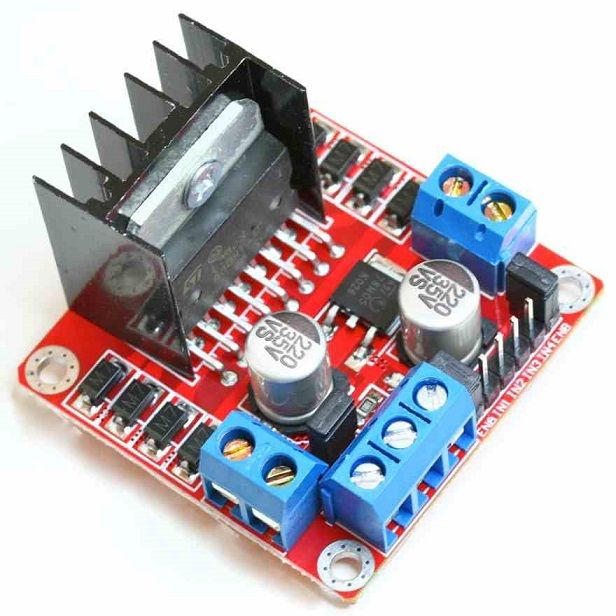
As mentioned above, we are using DC motors to control our lift. We have in all 3 motors and they are all connected to a L298 driver (see picture below) controlled by an Arduino Uno board.
Here is a link where you can buy the driver :
https://www.amazon.fr/L298-Motor-Driver/s?ie=UTF8&page=1&rh=i%3Aaps%2Ck%3AL298%20Motor%20Driver
We use 2 motors for the rollers to collect the blocks. In order to do so, each one has to turn in the opposite direction of the other but at the same speed. Thus we connected them to the same driver but inverted the pins of one motor compared to the other one. These motors don’t have an encoder so their only 2 pins are connected to the driver. We also have the third motor to make the lift go up and down. As we said before, we use the encoder to know where we have to stop so there are pins of the motor connected to the Arduino board. On the other hand the motor is also connected to the driver so we can control its speed, stop it and launch it.
The cage
The floors can rotate thanks to a dynamixel and a bearing wheel. To place the bearing wheel on the rotating axis we insert the last floor into the others floors with the bearing wheel between them as shown in the next figure :
External parts
Most of the part are home made (CNC, 3D printing) but some parts a bought on the market :
-
IGUS rail
- Small one
- Rail : Igus N Series, NS-01-17-300, Linear Guide Rail 17mm width 300mm length
- Carriage : Igus Linear Guide Carriage NW-02-17, N
- Big one :
- Rail : Igus N Series, NS-01-27-300, Linear Guide Rail 27mm width 300mm length
- Carriage : Igus Linear Guide Carriage NW-02-27, N
- Small one
-
Lift transmission
- Pitch (distance between teeth) : 2.032 mm
- Pulley : aluminium, Glass Filled PC Timing Belt Pulley, 6mm Belt Width x 2.032mm Pitch, 36 Tooth, Maximum Bore Dia. 5mm
- Timing belt : RS Pro, Timing Belt, 315 Tooth, 640.08mm Length X 6mm Width
-
Limit switch
- Snap Action Limit Switch, Roller Lever, Thermoplastic, NC, 125V
Authors
Crappe Martin
Hagopian Armen
The Cortex (small) Robot
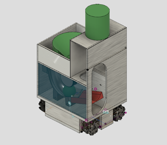
This year, the Eurobot task was water purification. As water is not practical around prototype electronics, they used balls to represent water. The balls of the same colour that is assigned to you during a match will represent clean/purified water whereas balls of the same colour as your opponents represent dirty water that has to be treated. To ease readability the word "balls" will be used synonymously with "water" for the rest of this article. We are also going to assume that the team colour assigned to our team is GREEN and therefore green balls = clean water and orange balls (the colour of the opponent team) = dirty water.
At the start of each match the Cortex robot has to collect 8 balls from two different containers on the playing field, sort them and then send them either to the "home tank" if they are green balls and into the reservoir if they are orange balls. We will take a look the mechanisms we put in place to collect, sort and send balls during each match for Eurobot 2018.
Ball Mechanism
Introduction
Initially, after much thought, we created a system composed of 3 basic parts and a colour detector. There are two parts that are mobile parts and one stagnant outer case. The system is divided into 4 compartments: the entry point, the colour sensor (CS) compartment, green trap compartment and the orange trap compartment. The colour detector is embedded in the stagnant outer case. Underneath the outer case is a moving plate controlled by an actuator (the dynamixel AX-12A) and a rotating "pusher" controlled by a stepper motor to move balls within the outer case.
Essentially there are 4 main steps for a ball to be separated in this system:
- The ball enters the mechanism at the entry point.
- The stepper motor activates and moves the ball to the CS compartment.
- The colour sensor detects the colour of the ball. Once the colour of the ball is known, the dynamixel AX-12A is activated and the opening of the mobile plate is moved into the corresponding colour position.
- The stepper motor activates and moves the ball into the green trap or orange trap.
The interest behind this idea is the fact that as the "pusher" is activated and moving another ball can enter at at the entry point and therefore creating a chain effect which we hoped would gain us time.
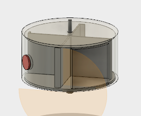
The outer case and colour sensor
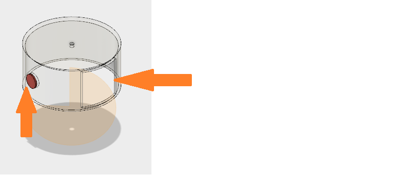
As you can see here we have the entry point and the colour sensor. How the colour sensor works and its corresponding code can be found in the sensors section.
The mobile plate
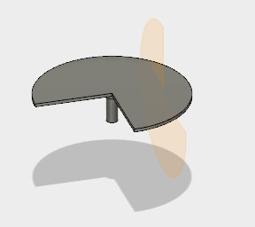
Control of the mobile plate was done with a dynamixel AX-12A.
The "pusher"
The pusher as well as the colour detector were eventually excluded from initial prototyping for the Cortex robot because of time constraints and on the basis of a strategic decision to simplify the mechanism for the qualifying stages. However, the link to an open-source library very useful for controlling stepper motors is supplied in this document under the actuator section as well.
Ball mechanism used in qualifying stages
This is the system that we used during qualifying stages which only makes use of a mobile plate and rounded edges on the sides and corners to guide the balls collected. The mobile plate was controlled by dynamixel and the corresponding code and application can be found under the actuators section of this report.
Ball Gun (Sending Mechanism)
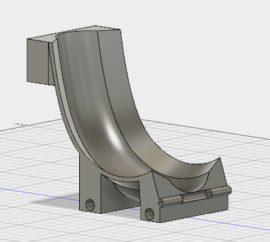
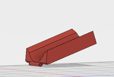
3D sketch
All the parts of the ball gun is designed on Fusion 360 and printed on a 3D printer except of the balls and the wheel.
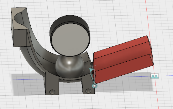
Why a ball gun?
For the 2018 contest, we had to collect and sort balls by color and then put all the balls collected in the color of the team previously known in a big tank that made reference of a water castle as the balls made reference of water itself. The more balls we threw in the tank, the more points we earned.
We choose to throw the balls with a gun made of a ramp for the direction of the ball and a wheel with a DC motor. as shown on the picture, you can see a fixed ramp, an adjustable ramp and the wheel.
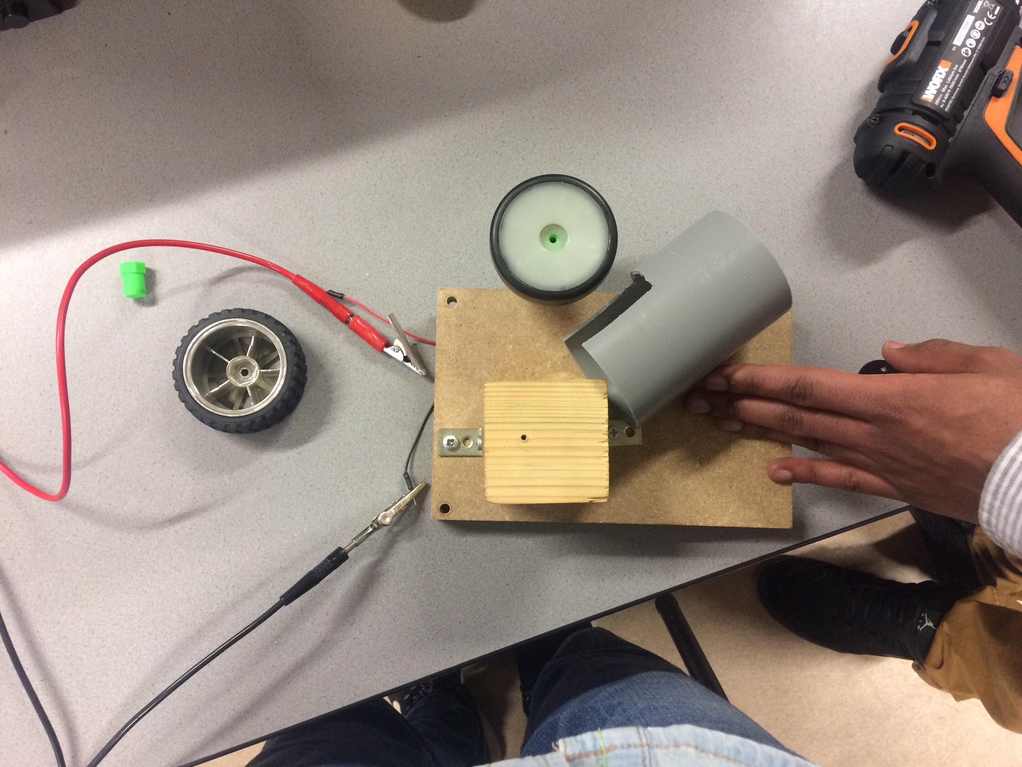
Construction step by step
After lots of discussions with the team, I decided to choose the ball gun to complete the task of throwing balls in the tank. So I first made a prototype of the ball gun made of wood and a small DC motor I found in the lab but for the first tests it appeared that the small DC motor wasn't powerfull enough. So I choose a more powerfull and a better speed motor as a Maxon motor found in the lab and the results were very conclusive.
The next step was to control the speed of the wheel so we could control the distance the ball make after throwing by the ball gun.
I used a small motor driver as the L293D which the specifications were in agreement with the needs of the DC motor.
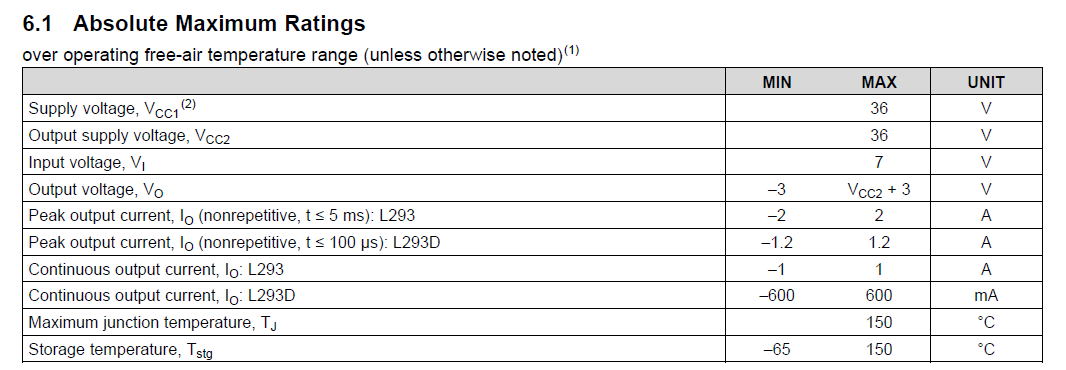
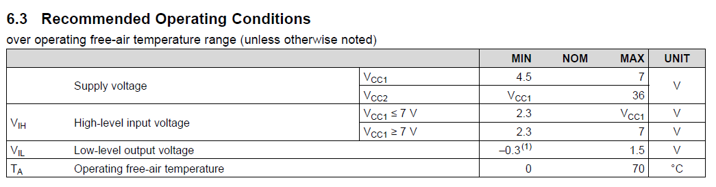
You can find the datasheet of the L293D here : https://github.com/Ecam-Eurobot/Tutorials/tree/StevenGaro-patch-1/src/mechanical/2018/BallGun_SRC
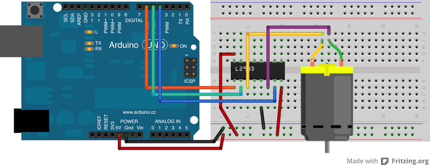
To control the H bridge driver, I used a simple arduino uno with a PWM signal so we could test different speeds of the motor.
The precision of the distance the ball make was made experimentaly when we did the different tests.
The code I first used to test the driver with the motor is the next code in arduino :
int inputPin = A0;  // set input pin for the potentiometer
int inputValue = 0; // potentiometer input variable

const int motorPin1  = 5;  // Pin 14 of L293
const int motorPin2  = 6;  // Pin 10 of L293

void setup() {
     // declare the ledPin as an OUTPUT:
     pinMode(motorPin1, OUTPUT);

}

void loop() {
     // read the value from the potentiometer:
     inputValue = analogRead(inputPin);

     // send the square wave signal to the LED:
     analogWrite(motorPin1, inputValue);

  digitalWrite(motorPin1, HIGH);
  delayMicroseconds(inputValue); // Approximately 10% duty cycle @ 1KHz
  digitalWrite(motorPin1, LOW);
  delayMicroseconds(1023 - inputValue);

}
When the tests were conclusive enough, we designed a ramp that fit in the robot correctly with an adjustable ramp for the ball to go higher or lower in case we need to modify the distance during the competition.
First we made the fixed ramp that comes from the ball sorting mecanism and end around the wheel.
After that we made a straight ramp that shows the ball the direction it must take.
And finaly, we designed a small piece that maintain the straight ramp from below and that you can adjust.
After that, all we had to do is to install the gun in the robot and make some tests to determine the best power to give as a PWM to the motor to throw the balls from the distance chosen in the tank and to incorporate the code of the ball gun in the main code of the robot.
Electronics
In the next chapters, we will describe all everything related to the electronics of the robots. Including:
- Technologies we used
- Printed circuit boards we designed
- How to use particular sensors
- How to use particular actuators
- ...
Introduction
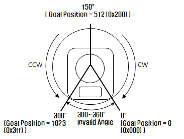
Dynamixels are servomotors with a working angle of 300° dispatched on values 0 to 1023.
They also have the particularity of beeing able to be used as DC motor. They have a very good motor torque what makes them efficient for a big number of applications. In our robots, we used them for the tasks the robots had to realise during the competition as :
- Sort balls of different colors
- Deploy an arm to push an object on wheels
- Deploy a platform on multiple floors to liberate cubic blocks
- Maintaining the blocks on every floor or not
- Actionate a gear to move blocks
The cabling is made with JST 3 pin connectors from a servomotor to another.
Here is a link on amazon to order some : https://www.amazon.fr/ensembles-Micro-connecteur-Fiche-150mm/dp/B01DU9OY40/ref=sr_1_2?ie=UTF8&qid=1525997056&sr=8-2&keywords=jst+connecteur+3+pin&dpID=51oVa4jux4L&preST=SY300_QL70&dpSrc=srch
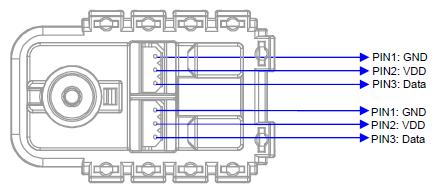
The Dynamixels have 2 locations for these connectors because it is possible to connect several servomotors in series and to control them with an addressing. These adresses are represented by unique ID for every dynamixel and it is possible to check with the software Dynamixel Wizard of Roboplus and a USB2Dynamixel.
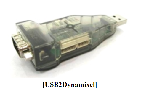
Thanks to this software, it is also possible to configurate the dynamixels (registers) like, among others, the baudrate of the servomotor and also to access a serie of informations in real time like the speed, the position, etc.
Description
Dynamixels are servomotors with a working angle of 300° dispatched on values 0 to 1023.
They also have the particularity of beeing able to be used as DC motor. They have a very good motor torque what makes them efficient for a big number of applications. In our robots, we used them for the tasks the robots had to realise during the competition as :
- Sort balls of different colors
- Deploy an arm to push an object on wheels
- Deploy a platform on multiple floors to liberate cubic blocks
- Maintaining the blocks on every floor or not
- Actionate a gear to move blocks
The cabling is made with JST 3 pin connectors from a servomotor to another.
Here is a link on amazon to order some : https://www.amazon.fr/ensembles-Micro-connecteur-Fiche-150mm/dp/B01DU9OY40/ref=sr_1_2?ie=UTF8&qid=1525997056&sr=8-2&keywords=jst+connecteur+3+pin&dpID=51oVa4jux4L&preST=SY300_QL70&dpSrc=srch
The Dynamixels have 2 locations for these connectors because it is possible to connect several servomotors in series and to control them with an addressing. These adresses are represented by unique ID for every dynamixel and it is possible to check with the software Dynamixel Wizard of Roboplus and a USB2Dynamixel.
Thanks to this software, it is also possible to configurate the dynamixels (registers) like, among others, the baudrate of the servomotor and also to access a serie of informations in real time like the speed, the position, etc.
Specifications
- Weight : 53.5g (AX-12/AX-12+), 54.6g (AX-12A)
- Dimension : 32mm * 50mm * 40mm
- Resolution : 0.29°
- Gear Reduction Ratio : 254 : 1
- Stall Torque : 1.5N.m (at 12.0V, 1.5A)
- No load speed : 59rpm (at 12V)
- Running Degree : 0° ~ 300° or Endless Turn
- Running Temperature : -5℃ ~ +70℃
- Voltage : 9 ~ 12V (Recommended Voltage 11.1V)
- Command Signal : Digital Packet
- Protocol Type : Half duplex Asynchronous Serial Communication (8bit,1stop,No Parity)
- Link (Physical) : TTL Level Multi Drop (daisy chain type Connector)
- ID : 254 ID (0~253)
- Communication Speed : 7343bps ~ 1 Mbps
- Feedback : Position, Temperature, Load, Input Voltage, etc.
- Material : Engineering Plastic
Dynamixel Wizard
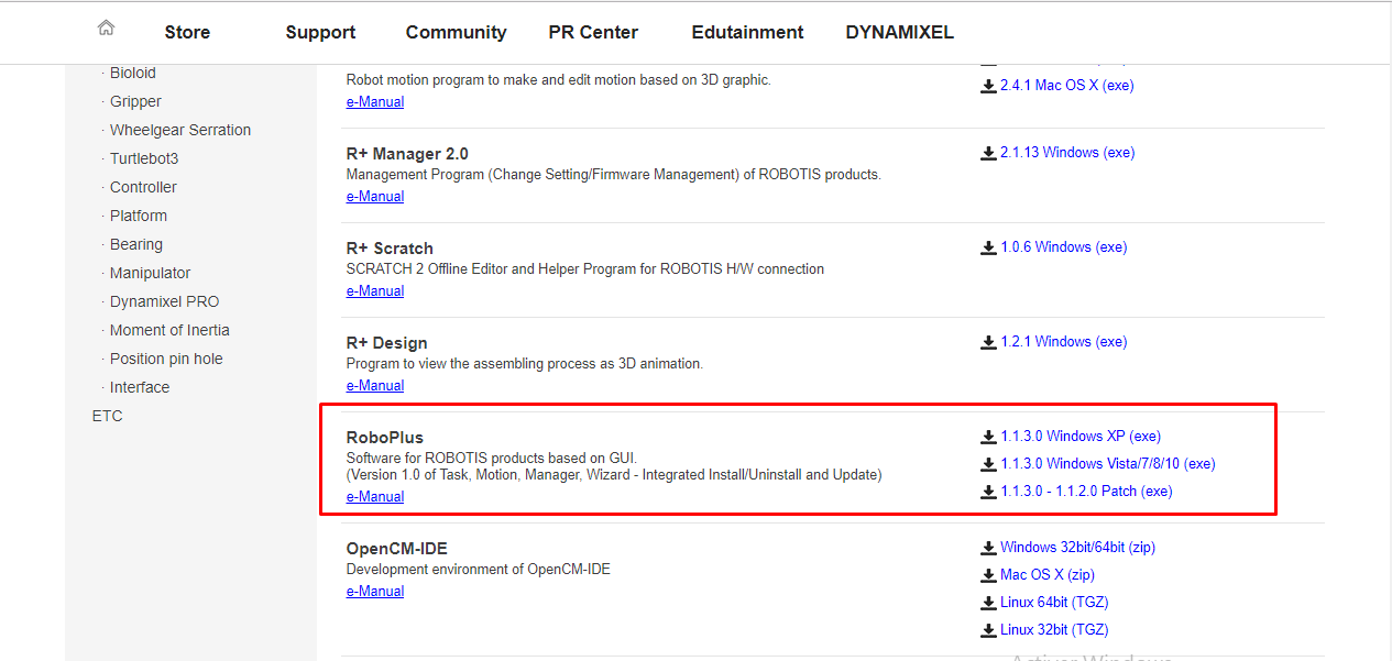
- Download and install the software "Roboplus" on the website www.robotis.com when going in Support>Download>Software>Roboplus
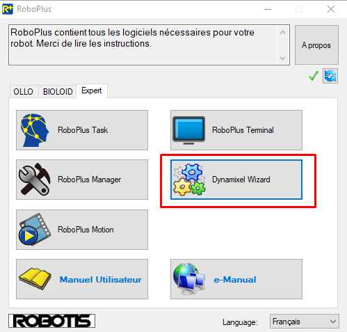
- Launch the software and clic on Dynamixel Wizard
- Insert the USB2Dynamixel in the USB port of the computer
- Connect the 3 pins JST connector in the USB2Dynamixel (TTL side) ansd the dynamixel to verifie or configure
- Select « TTL » with the switch on the USB2Dynamixel
- Supply the dynamixel separately in its working voltage (9-12V, recommanded 11,1V) with the second port of the dynamixel
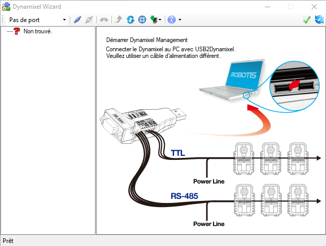
- Select the port of your computer where the USB2Dynamixel is connected
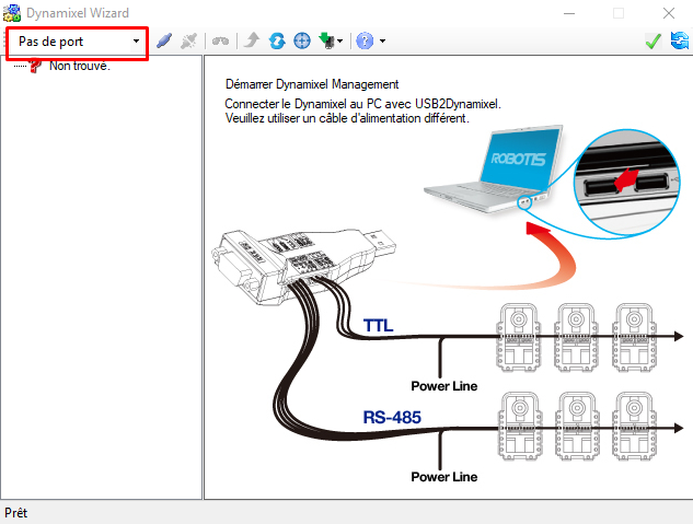
- Clic on "Open Port"
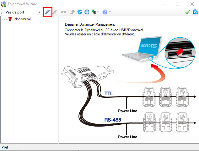
- Make a basic research of the dynamixel to find its ID
-
It is also possible to make advanced research on other baudrates in case of the basic research is not working
-
Once the dynamixel found, selct it on the left side of the window
-
The details of the informations of the dynamixel appears
-
in these details, it is possible to modify the configuration of the dynamixel like its ID, its communication speed (baudrate), its working speed, etc, or also to control it in real time.
Examples of use
To use the dynamixels, it is necessary to download first the library "AX_12A_servo_library" that you can find on the github of eurobot here : https://github.com/Ecam-Eurobot/Tutorials/tree/master/src/electronics/actuators/Dynamixels_SRC
You'll have to extract it and place it in Documents/Arduino/libraries.
To configure the dynamixels, we'll use the Arduino software app.
This library possess 4 exemples of use of the dynamixel :
- Blink : example of control of the red led you can find in the back of every dynamixel
- Move : example of control of the dynamixel in servomotor mode by giving it a position
- EndlessTurn : example of use in DC motor mode (or wheel mode)
- ReadRegister : usefull to dispaly the contents of the registers of the dynamixel
These examples are located in Fichier>Exemples>AX-12A on the Arduino app on your computer.
After selecting one of the examples, you have to include the library AX-12A without declaring a specific path because the library is located in the fold "libraries" of the fold "Arduino".
After that you have to configure 3 lines in the code that respond to the needs of the configuration of the connected dynamixel you want to configure :
#define DirectionPin  (10u)
#define BaudRate      (1000000ul)
#define ID            (1u)
"DirectionPin" is used to indicate the communication direction of the dynamixel. 10u is for writing in the registers so you don't have to change the value.
"BaudRate" defines the communication speed used ( and configurate before with the Dynamixel Wizard)
"ID" represents the ID of the dynamixel that you checked or configured before for the addressing.
Application with ROSserial
As explained in the section "Ball Mechanism", one dynamixel was used to control the separation of coloured balls (one colour representing dirty water and the other clean water). This dynamixel has three main positions:
- Initial_pos_purifier (blocked or closed) position
- Clean ball position (opens trap for green balls as in our earlier example)
- Dirty ball position (Open trap for orange balls as in our earluer example)
Another task that Cortex robot had was to push a bee for the foraging task. This meant we needed a mechanical hand that extended from the robot in order to push the bee. We used a dynamixel for this action as well. This dynamixel has two main positions:
- initial_pos_bee (embedded inside robot)
- push_pos (extended from robot)
We calibrated these positions using the angle diagrams supplied in the data sheet and the good old "trial and error method".
Schematic block Diagram
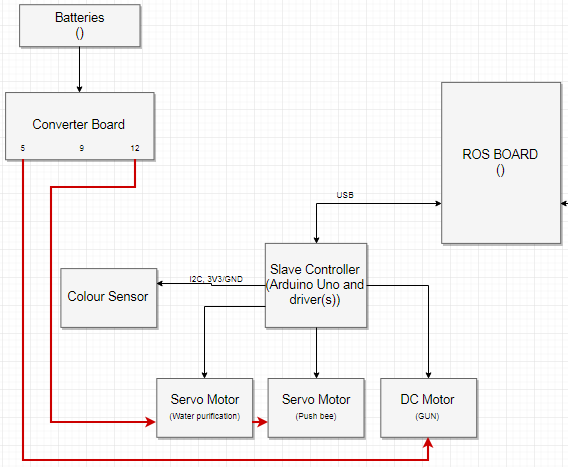
The communication between the ROS board (Rasberry pi with ROS installed) and the Arduino Uno board that controls the tasks of the Cortex robot takes place over a USB serial communication better known as ROSserial. The concepts behind ROSserial are explored in detail in the chapter "Software" of this document. I personally recommend reading that section to better understand the code presented here.
The three main actions of the Arduino board are:
- Separate dirty balls from clean balls (without colour detection and pusher in qualifying stages)
- Push bee
- Drive DC motor to shoot clean balls into home tank.
These actions are activated and controlled fully by the ROS board. That is, if the ROS board wants to push the bee, the Arduino board must be ready to receive the message and activate the right actuators in order to push the bee.
! Attention: It is imperative to program the dynamixels to the right baudrate first! This can be done using the USB2Dynamixel and Dynamixel Wizard software as explained earlier. We had problems controlling the dynamixels via the ROS board at the default baudrate of 1000000 BPS. The communication speed that worked best was the default baudrate used by ROS on the Raspberry pi, 57600 BPS. After setting the dynamixel in the wizard, all you have to do is change the baudrate in the code from 1000000ul to 57600ul. (Note: 1000000ul works fine when controlling the dynamixels with only the Arduino board, hmm).
! Attention: These dynamixels use UART to communicate, if you use the Arduino Uno which only has one on board UART module then you will not be able to use the serial monitor at the same time! DO NOT PUT SERIAL.BEGIN IN SETUP when you want to work with the dynamixels on an Arduino Uno. The best case would be to use a board with more than one UART module, allowing you to control the dynamixels independent of the serial monitor.
Code
#include <ros.h>
#include <std_msgs/Bool.h>
#include <std_msgs/Int16.h>
#include <AX12A.h>

//Ax-12A IDs and baudrate
#define DirectionPin  (10u)
#define BaudRate     (57600ul)
#define ID1          (7u)  //water purification
#define ID2          (1u)  //bee

//Gun pin definitions
#define i1            5
#define i2            4
#define ena_pwm       9     //PWM pin at 490Hz

//Water purification definitions
#define clean_ball_position 90
#define dirty_ball_position 916
#define initial_pos_purifier 512
//int initial_pos_purifier = 512;


//water purification declarations
int servo_speed = 500; //speed for ax-12a movement

//Dynamixel AX-12A definitions and global variables
//for control of valve used to separate/purify balls/water.
//@param valve_pos is controlled by ROS board.
int initial_pos_bee = 552;
int valve_pos;

//Start ROS handle.
ros::NodeHandle nh;

void moveBee( const std_msgs::Bool & position_msg){

  // Bool variable decides whether to push bee
  // or return to initial position. False = initial position
  // True = push bee position
  bool pushbee = false;
  int pushbee_pos = 30;   // initial/push position for bee still needs to be calibrated

  pushbee = position_msg.data;
  if(pushbee){
    //ax12Move(ID2, pushbee_pos, servo_speed);
    ax12a.moveSpeed(ID2, pushbee_pos, servo_speed);
    }
  else {
    //ax12Move(ID2, initialpos, servo_speed);
    ax12a.moveSpeed(ID2, initial_pos_bee, servo_speed);
    }
}

void moveValve(const std_msgs::Int16 & pos_msg){

  valve_pos = pos_msg.data;
  if(valve_pos == 1){
    ax12a.moveSpeed(ID1, clean_ball_position, servo_speed);
    }
  else if (valve_pos == 2){
    ax12a.moveSpeed(ID1, dirty_ball_position, servo_speed);
    }
  else if(valve_pos == 3){
    ax12a.moveSpeed(ID1, initial_pos_purifier, servo_speed);
    }
}

void shootGun( const std_msgs::Int16 & dutycycle_msg){
   //Gun declarations. @param dutycycle (0-255) is controlled
  //by ROS board.
  int dutycycle = 0;
  dutycycle = dutycycle_msg.data;

  //direction
  digitalWrite(i1, LOW);
  digitalWrite(i2, HIGH);

  //Drive
  analogWrite(ena_pwm, dutycycle);
}

//Move purifier to and fro in order to make
//sure all balls enter compartment
void shake(void);

ros::Subscriber<std_msgs::Bool> bee_ctrl("bee_control", &moveBee);
ros::Subscriber<std_msgs::Int16> ballseparator_ctrl("water_purification", &moveValve);
ros::Subscriber<std_msgs::Int16> gun_ctrl("gun_control", &shootGun);


void setup() {

  pinMode(ena_pwm , OUTPUT);
  pinMode(i1, OUTPUT);
  pinMode(i2, OUTPUT);

  //Start-up
  ax12a.begin(BaudRate, DirectionPin, &Serial);
  //Remove endless rotation
  ax12a.setEndless(ID1, OFF);
  ax12a.setEndless(ID2, OFF);
  //move into initial position
  ax12a.moveSpeed(ID1, initial_pos_purifier, servo_speed);
  ax12a.moveSpeed(ID2, initial_pos_bee, servo_speed);

  nh.initNode();

  nh.subscribe(bee_ctrl);
  nh.subscribe(ballseparator_ctrl);
  nh.subscribe(gun_ctrl);
}

//the loop contains is empty.
void loop() {
  nh.spinOnce();
  //delay(50);
  //shake();
}


void shake(void)
{
    int dir = 0;
    int current_pos = ax12a.readPosition(ID1);

    if (valve_pos == 1){
    if (dir == 0){
      if (current_pos != clean_ball_position + 200){
        ax12a.moveSpeed(ID1, clean_ball_position + 200, servo_speed);
      }
      else {
        dir = 1;
      }

    }
    else if (dir == 1){
      if (current_pos != clean_ball_position){
        ax12a.moveSpeed(ID1, clean_ball_position - 200, servo_speed);
      }
      else {
        dir = 0;
      }
    }

  }
  if (valve_pos == 2){
    if (dir == 0){
      if (ax12a.readPosition(ID1) != dirty_ball_position + 200){
        ax12a.moveSpeed(ID1, dirty_ball_position - 200, servo_speed);
      }
      else {
        dir = 1;
      }

    }
    else if (dir == 1){
      if (ax12a.readPosition(ID1) != dirty_ball_position){
        ax12a.moveSpeed(ID1, dirty_ball_position + 200, servo_speed);
      }
      else {
        dir = 0;
      }
    }

  }
}
Note: ROS library packages are bulky and can get very big, adding more #includes or libraries to your code will mean more global variables to your overall project. Make sure that your board, Uno, Nano etc. has enough memory space) for the large amount of global variables. I invite you to compile this code and load it on an Arduino board. Check the memory details after loading, you will see that we're already almost at the limit ! Think about this for the future.
How it works
Libraries
Include all libraries that are necessary for the application but be sure to include ros.h first! Here we will need the AX12A library to control the dynamixel servo motor. We also need certain source code from the ROSserial std_msgs (allows for communication over ROSserial) package. These source code files that we include will determine the type (int, foat64, String etc..) of the messages that will be exchanged between the Arduino board and the ROS board.
To control the position of the "bee dynamixel" we only need a true or false signal from ROS but for the "water purifier" we need three positions so we'll rather go for the type int here. The choice is yours.
Note: We had difficulties working with the std_msgs: Int8 and String when programming with the dynamixels so we settled with Int16 and Bool.
#include <ros.h>              //ROS packages
#include <std_msgs/Bool.h>     //ROS std messages needed for com
#include <std_msgs/Int16.h>
#include <AX12A.h>            //Dynamixel control
Declarations and pin definitions
Declare as many variables as possible through the #define method in order to save global variable space on the Arduino Uno, for example:
//Gun pin definitions
#define i1            5
#define i2            4
#define ena_pwm       9     //PWM pin at 490Hz

//water purification declarations
int servo_speed = 500;      //speed for ax-12a movement
Don't forget to create the ROS node!
//Start ROS handle.
ros::NodeHandle nh;    //Create a ROS node
Create callback function
The Arduino board is seen as a node by the ROS board. In order to receive commands from it we need to subscribe to a topic to see what the ROS board has sent us. This is how we create a topic and a callback function:
//For ROS, the name of the topic is gun_control and the ROS board can send
//messages only of type Int16. The name of the function in Arduino that needs
//to be called every time we receive a message is shootGun
ros::Subscriber<std_msgs::Int16> gun_ctrl("gun_control, &shootGun);
Now we need to implement the call back function, for example the callback function for the water_purification topic:
void moveValve(const std_msgs::Int16 & pos_msg){

  valve_pos = pos_msg.data;   //Get data sent from ROS
  if(valve_pos == 1){
    ax12a.moveSpeed(ID1, clean_ball_position, servo_speed); //cross-reference library for more info
    }
  else if (valve_pos == 2){
    ax12a.moveSpeed(ID1, dirty_ball_position, servo_speed);
    }
  else if(valve_pos == 3){
    ax12a.moveSpeed(ID1, initial_pos_purifier, servo_speed);
    }
}
Set-up
We need to setup the dynamixel, subscribe to the our topics and we need to initialise the ROS node we created.
  //Start-up
  ax12a.begin(BaudRate, DirectionPin, &Serial);
  //Remove endless rotation
  ax12a.setEndless(ID1, OFF);
  ax12a.setEndless(ID2, OFF);
  //move into initial position
  ax12a.moveSpeed(ID1, initial_pos_purifier, servo_speed);
  ax12a.moveSpeed(ID2, initial_pos_bee, servo_speed);

  nh.initNode();

  nh.subscribe(bee_ctrl);
  nh.subscribe(ballseparator_ctrl);
  nh.subscribe(gun_ctrl);
loop
Keep it simple. Do not over load the loop. We want to nh.spinOnce to to be called as often as possible without interruption.
nh.spinOnce(); //Checks topics that we subscribed to and calls callback function if ROS board has published something correctly.
What ROS needs to send
To properly implement this code, you will need a ROS board and an Arduino board. The default baudrate is 57600 with ROS. ROS needs to publish:
- true or false to the topic "bee_ctrl" to position dynamixel
- 1, 2 or 3 to the topic "ballseparator_ctrl" to position dynamixel
- 0-255 to set the duty cycle of the PWM signal at pin 9 of the Arduino.
References
-
e-manual : http://support.robotis.com/en/
-
youtube vidéo for all the steps of the use of the Dynamixel Wizard : https://www.youtube.com/watch?v=YJ9b68hx5Qc&version=3&hl=ko_KR
-
website of the manufacturer : http://en.robotis.com
-
AX-12A library : https://github.com/ThingType/AX-12A-servo-library
Sonar
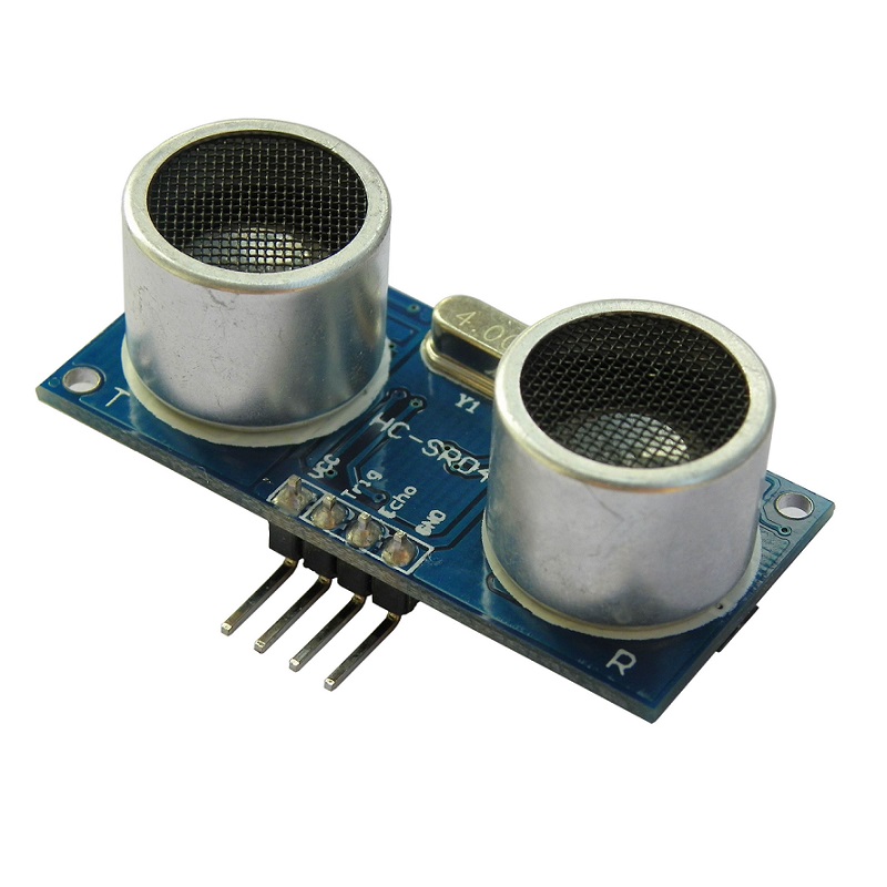
A sonar is a sensor allowing you to measure the distance to an obstacle thanks to high frequency waves. To keep correct measured values it is better to use the sensor we chose between 2cm and 400cm. The model of our sonar is HC-SR04. There are 4 pins on this sensor : TRIG, ECHO, VCC and GND (as you can see on the picture below).
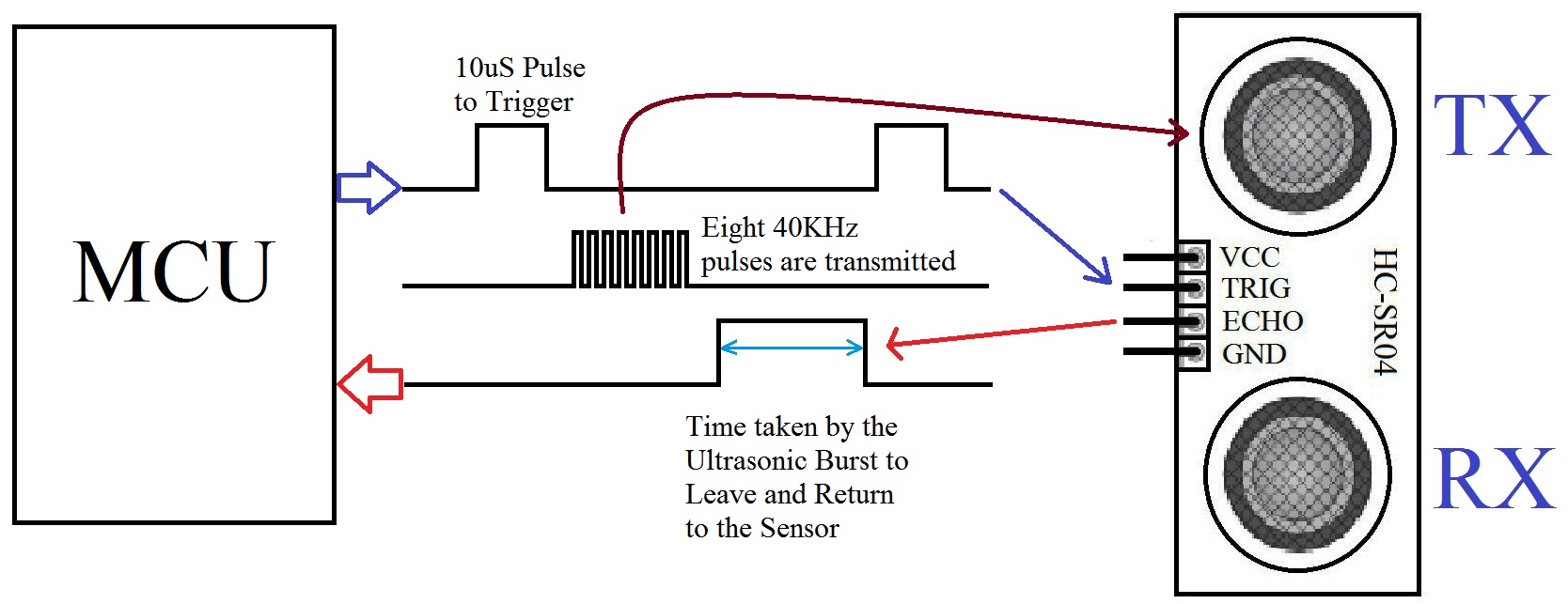
It contains a transmitter and a receiver. The distance measure is pretty simple. Firstly, you have to send a signal on the TRIG pin so the sonar emits a wave of 8 pulses at 40kHz. Then the ECHO pin is set to the «HIGH» level until the emitted signal goes to the obstacle and comes back to the sensor (as you can see on the following picture).
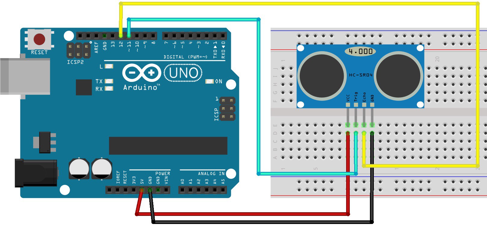
Of course, you have to connect the sensor to a microcontroller. You can connect the VCC to the 5V pin of your board, the GND to the ground pin and the TRIG and ECHO to digital pins of your controller as illustrated on the picture below.
Finally it is also important to know that the measuring angle with the HC-SR04 sonar is 30 degrees. Which is short, so the sonar can only see in front of him
All these information are also explained in the following websites :
https://www.gotronic.fr/pj2-hc-sr04-utilisation-avec-picaxe-1343.pdf
https://wiki.mchobby.be/index.php?title=HC-SR04
http://web.eece.maine.edu/~zhu/book/lab/HC-SR04%20User%20Manual.pdf
Here is an online store where you can buy this sensor :
https://shop.mchobby.be/proximite/561-senseur-ultrason-hc-sr04-3232100005617.html
Images references :
http://www.instructables.com/id/HC-SR04-Ultrasonic-Sensor-With-Raspberry-Pi-2/
https://randomnerdtutorials.com/complete-guide-for-ultrasonic-sensor-hc-sr04/
Tutorial
Simple Arduino code
To be able to test the simple code showed in this part you have to connect the sonar sensor to your Arduino Uno board as showed on the third picture hereinabove. You also have to connect the TRIGG pin of the sonar to the pin 12 on your Arduino board and the ECHO pin of the sonar to the pin 13 on the Arduino board. Of course you can change these values on the following code if needed.
You are now ready to upload the code :
#define TRIGG 12 // Broche TRIGGER
#define ECHO 13    // Broche ECHO
                                               // definition du Timeout
const long TIMEOUT = 25000UL; // 25ms = ~8m à 340m/s

float son= 340.0 / 1000; //vitesse du son dans l'air (mm/µs)

void setup() {

  pinMode(TRIGG, OUTPUT);  //Configuration des broches
  digitalWrite(TRIGG, LOW); // La broche TRIGGER doit être à LOW au repos
  pinMode(ECHO, INPUT);

  Serial.begin(9600); //Démarrage de la liaison série
}

void loop() {

  digitalWrite(TRIGG, HIGH); // Lance une mesure de distance en envoyant
  delayMicroseconds(10);  //une impulsion HIGH de 10µs sur la broche TRIGGER
  digitalWrite(TRIGG, LOW);

  int mesure = pulseIn(ECHO, HIGH, TIMEOUT); // Mesure le temps entre
                                          // l'envoi de l'ultrason et sa réception

  float distance_mm = mesure / 2.0 * son; //calcul de la distance grâce au temps
                                      //on divise par 2 car le son fait un aller-retour

  Serial.print("Distance: "); //Affichage des résultats
  Serial.print(distance_mm);
  Serial.println("mm");

  delay(500); //temps entre chaque mesure (ms)
}
To verifiy if everything is working correctly after uploading the code you can click on the Serial monitor icon on the Arduino IDE (as shown on the picture below) to see what distance the sonar returns in milimeters.
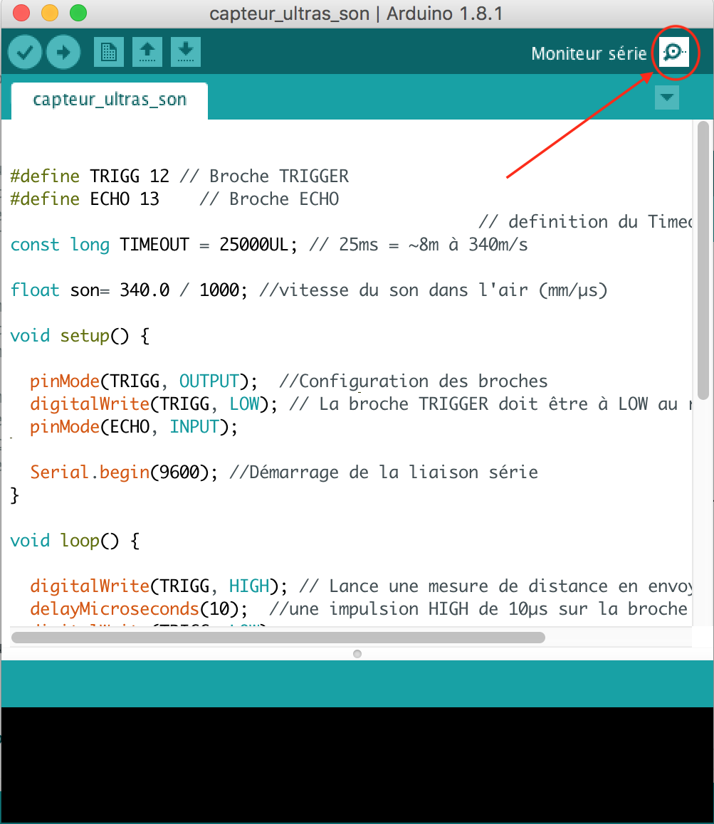
Link to the code on Ecam Eurobot Github :
https://github.com/Ecam-Eurobot/Eurobot-2018/blob/ultrasound/arduino/sonar_simple_test_no_ROS.ino
Go check in ROS and Arduino chapter for combining Sensor, Arduino and ROS
Reflexion
This kind of sensor need that the signal leaves the Trigger head and go back to the Echo head.
If the signal leaves the Trigger head and doesn't come back to the Echo head then the sensor decide that there is nothing.
So when there is an obstacle in front of the sensor this obstacle must be in front of the 2 head of the sensor else for the sensor there is no obstacle.
Before putting the sensor on the robot think about this, is it best to put the sensor horizontally or vertically?
The colour Sensor
There are a wide range of colour sensors currently available today. After studying various sensors that are currently on the market we decided to use the RGB Colour Sensor with IR filter and White LED from Adafruit mostly because of its size, cross-platform support (including python code https://learn.adafruit.com/adafruit-color-sensors/circuitpython-code) and the fact that it communicates with I2C, the communication bus we had planned on using initially. Eventually we bought the even smaller version, the Flora Colour Sensor with White Illumination LED, both of them use the same integrated circuit, the Adafruit TCS34725.
On board circuitry includes:
- 3.3V regulator so you can power the breakout with 3-5VDC safely and level shifting for the I2C pins so they can be used with 3.3V or 5V logic
- neutral 4150°K temperature LED with a MOSFET driver on board to illuminate what you're trying to sense.
- An IR blocking filter, localized to the color sensing photodiodes, minimizes the IR spectral component of the incoming light and allows colour measurements to be made more accurately
More information on this colour sensor can be found here
Assembly
On the Flora:
3.3v -> 3v (red wire)
GND -> GND (black wire)
SDA -> SDA (white wire)
SCL -> SCL (green wire)
On the Arduino:
Connect SCL    to analog 5
Connect SDA    to analog 4
Connect VDD    to 3.3V DC
Connect GROUND to common ground
The library
To start working with this sensor it is advised to start by downloading the Arduino library from the github link provided in the references and install it into the library folder of your Arduino IDE. Hint: the right Arduino folder is usually found in My Documents. The library is an object-orientated library that allows to create a colour sensor object and access all its capabilities through its methods.
The Code
After installing the library, the best thing to do is start with the examples already provided by the library. I started with and tweaked the mostly the Colorview code because it allows to give us values between 0 and 255 for the different RGB colours (not 100% accurate but accurate enough) of the object being detected. here's an example:
#include <Wire.h>                  //include Wire.h to be able to communicate through I2C on Arduino board
#include "Adafruit_TCS34725.h"     //Colour sensor library

//Create colour sensor object declaration, to see effects of different integration time and gain
//settings, check the datatsheet of the Adafruit TCS34725.
Adafruit_TCS34725 tcs = Adafruit_TCS34725(TCS34725_INTEGRATIONTIME_50MS, TCS34725_GAIN_4X);

void setup() {
  Serial.begin(9600);
  Serial.println("Color View Test!");

  //Start-up colour sensor
  if (tcs.begin()) {
    Serial.println("Found sensor");
  } else {
    Serial.println("No TCS34725 found ... check your connections");
    while (1); // halt!
  }
}


void loop() {

  uint16_t clear, red, green, blue;
  uint16_t upperrangeG[3] = {100, 153, 71};
  uint16_t lowerrangeG[3] = {50, 104, 52};
  uint16_t upperrangeO[3] = {216,75,44};
  uint16_t lowerrangeO[3] = {155, 60, 32};

  //Collect raw data from integrated circuit using interrupts
  tcs.setInterrupt(false);      // turn on LED

  delay(60);  // takes 50ms to read

  tcs.getRawData(&red, &green, &blue, &clear);
  tcs.setInterrupt(true);  // turn off LED

  // Figure out some basic hex code for visualization
  uint32_t sum = clear;
  float r, g, b;
  r = red;
  r /= sum;
  g = green;
  g /= sum;
  b = blue;
  b /= sum;
  r *= 256; g *= 256; b *= 256;
  Serial.print("\t");

  Serial.print((int)r, HEX); Serial.print((int)g, HEX); Serial.print((int)b, HEX);
  Serial.println();

  Serial.print((int)r ); Serial.print(" "); Serial.print((int)g);Serial.print(" ");  Serial.println((int)b );

  if((r < upperrangeG[0] && g < upperrangeG[1] && b < upperrangeG[2]) || (r > lowerrangeG[0] && g > lowerrangeG[1] && b > lowerrangeG[2])){
    delay(50);
    Serial.print("Green");
  }
  if((r < upperrangeO[0] && g < upperrangeO[1] && b < upperrangeO[2]) || (r > lowerrangeO[0] && g > lowerrangeO[1] && b > lowerrangeO[2])){
    delay(50);
    Serial.print("Orange");
  }
}
How it works
After creating and setting up the colour sensor, we need to first set the upper and lower RGB ranges of the goal colour we want to detect. As we know, we don't have the best accuracy with colours sensors but we can try to isolate the colours we want through trial and error and make sure other colours are not detected instead of our goal colour. Here is the definition of the ranges for orange and green detection:
  uint16_t clear, red, green, blue;
  uint16_t upperrangeG[3] = {100, 153, 71};
  uint16_t lowerrangeG[3] = {50, 104, 52};
  uint16_t upperrangeO[3] = {216,75,44};
  uint16_t lowerrangeO[3] = {155, 60, 32};
Then we need to calculate the RGB colours between 0 and 255:
  // Figure out some basic hex code for visualization
  uint32_t sum = clear;
  float r, g, b;
  r = red;
  r /= sum;
  g = green;
  g /= sum;
  b = blue;
  b /= sum;
  r *= 256; g *= 256; b *= 256;
This program prints the RGB values of all colours detected by the sensor but will print "Green" or "Orange" if the colour detected is found within the specified range limits.
 if((r < upperrangeG[0] && g < upperrangeG[1] && b < upperrangeG[2]) || (r > lowerrangeG[0] && g > lowerrangeG[1] && b > lowerrangeG[2])){
    delay(50);
    Serial.print("Green");
  }
References
- Commercial page: https://www.adafruit.com/product/1356
- Online tutorial: https://learn.adafruit.com/adafruit-all-about-arduino-libraries-install-use
- Library: https://github.com/adafruit/Adafruit_TCS34725
- Datasheet: https://cdn-shop.adafruit.com/datasheets/TCS34725.pdf
The Mouse
This is a pc mouse. It gives a travel distance in x-axis and y-axis. It can't see rotation.
Application
If the mouse is connect in a Linux os, we can read the values in dev/input/mice.
import struct

with open("/dev/input/mice","rb") as fd:
    while True:
        # unpack data to have x and y
        y,x = struct.unpack("xbb",fd.read(3))
The distance given is not a distance in cm, we need to use a multiplication parameter to have the distance in cm.
We test the it on the 2019 eurobot.
You can find the files with ROS in the little_robot branch of Eurobot-2019, little_robot/ROS_packages/R&D/mouse/src.
Pros
- Distance traveled compute on the field.
Cons
- The raspberry must be fast enough.
- It's not better than the encoder of the mechanum wheels.
- It didn't see the rotations.
Printed Circuit Boards
last updated on May 11, 2018
Three types of printed circuit boards were developed for our two robots. The following section presents these boards, it utilities and it conception and gives you all the necessary elements to understand, recreate and use it.
Starting Board
last updated on May 11, 2018
Inspired by past version of the starting board
The utility of this PCB is to gather the component serving to the start sequence. Normally this is the only interface with the robot during the competition.
First, we used three switches for configuring three main points of our robot :
-
Team configuration We have to setup the starting side for the next match to the robot. It behaviour is different if the robot play as the green or the orange team. Consequently, this switch set this point before the match start.
-
Strategy Configuration It makes possible to choose between two kinds of implemented strategies before the match. For example, just before the start, we have the possibility of aggressive or defensive strategy, function of the opponent.
-
Initialisation Switch
This switch launches an initialisation sequence. After the power up of the robot and before its first move, we wanted to have the possibility to check all different robot's systems. This switch indicates with a DEL if all systems are operational. This is a kind of automatic check list before the match and the first move of the robot.
All these switches are linked to two DEL. First one to electrically confirm switches' position and the associated setting and the second one used to have the response of the robot operating system. With these two LEDs, we are sure that our robot understood all these parameters.
Useful information
- Correspondence
Strategy
Pin 1 - UP = GREEN = 0 (out raspberry) - DOWN = RED = 1 (out raspberry)
Initialisation
Pin 2 - UP = GREEN = 0 (out raspberry) - DOWN = RED = 1 (out raspberry)
Team
Pin 3 - LEFT = GREEN = 1 (out raspberry) - RIGHT = RED = 1 (out raspberry)
Start
Pin 4 - piece IN = 0 (out raspberry) - piece OUT = 1 (out raspberry)
- Switch placement
The emplacement is taken when the splayed side is on the right then :
- Strategy switch is in the upper left corner
- Initialisation switch is on the right side of the strategy switch
- Team switch is in the lower left corner
Finally, the starter switch is plugged on the board. It consists of a relay, sending a binary information to the ROS operating system. Linked to a 0.5m cable, this system allows to launch the match sequence pulling on it.
Getting Started
The following code is launched with ROS (if you haven't read yet this section, it might be tricky) this is a simplified version of the code used in 2018 robots. The aim of this code is the setting of a parameter in a configuration file in the first place, next the code publish on the start topic when the start switch is pulled. This last action indicates to all script listening this topic the beginning of a game.
import sys
import random
import rospy
from std_msgs.msg import Empty

raspberry = "-r" in sys.argv

pi = None
# If passed the -r argument, load the rapsberry libs
if raspberry:
    import pigpio
    pi = pigpio.pi()

rospy.init_node('startup_conf')

# Robot
robot = rospy.get_param("/robot")

pub_start = rospy.Publisher('start', Empty, queue_size=1)
pub_reset = rospy.Publisher('reset', Empty, queue_size=1)


# GPIO PIN CONFIGURATIONS
# This pin will be used to configure the team
pin_team = 23

# This pin will be used to drive a led to indicate that the team has been set correctly in ROS
pin_team_feedback = 21

# This pin will be used to drive a led to indicate that the start is understood by ROS
pin_strategy_feedback = 20

# This pin will be used to launch robot
pin_start = 12

# Function to set team parameter in the configuration file
def update_team(gpio, level, tick):
    if raspberry:
        if level:
            rospy.set_param("/team", "red")
            rospy.set_param("/reset/position", rospy.get_param("/start/{}/red/position".format(robot)))
            pi.write(pin_team_feedback, 1)
        else :
            rospy.set_param("/team", "green")
            rospy.set_param("/reset/position", rospy.get_param("/start/{}/green/position".format(robot)))

   # Blink 2 times for acknowledge
            pi.write(pin_team_feedback, 0)
    else:
        choice = random.choice(["green", "red"])
        team = rospy.set_param("/team", choice)
        rospy.logwarn("Setting team automatically to: " + choice)
        if team == "green":
            rospy.set_param("/reset/position", rospy.get_param("/start/{}/green/position".format(robot)))
        elif team == "red":
            rospy.set_param("/reset/position", rospy.get_param("/start/{}/red/position".format(robot)))

    reset()


publish = True

# If high level on start pin this function publish on the start topic
def start(gpio, level, tick):
    global publish
    rospy.sleep(0.2)
    if raspberry and not pi.read(pin_start):
        if publish :
            pi.write(pin_strategy_feedback, 1)
            pub_start.publish(Empty())
            publish = False

# Function to reset all set parameters
def reset():
    pub_reset.publish(Empty())
    if raspberry:
        if pi.read(pin_start):
            global publish
            publish = True
            pi.write(pin_strategy_feedback, 0)

com = False
init = True

if raspberry and init:
    pi.set_mode(pin_team, pigpio.INPUT)
    pi.set_mode(pin_start, pigpio.INPUT)
    pi.set_mode(pin_team_feedback, pigpio.OUTPUT)
    pi.set_mode(pin_strategy_feedback, pigpio.OUTPUT)
    pi.set_pull_up_down(pin_start, pigpio.PUD_DOWN)
    pi.set_pull_up_down(pin_strategy_feedback, pigpio.PUD_DOWN)
    teamInterrupt = pi.callback(pin_team, pigpio.EITHER_EDGE, update_team)
    startInterrupt = pi.callback(pin_start, pigpio.EITHER_EDGE, start)

    update_team(None, pi.read(pin_team), None)
else:
    rospy.sleep(1)
    update_team(None, None, None)

while not rospy.is_shutdown():
    pass
Below, you have the circuit to implement between the board and the raspberry running ROS
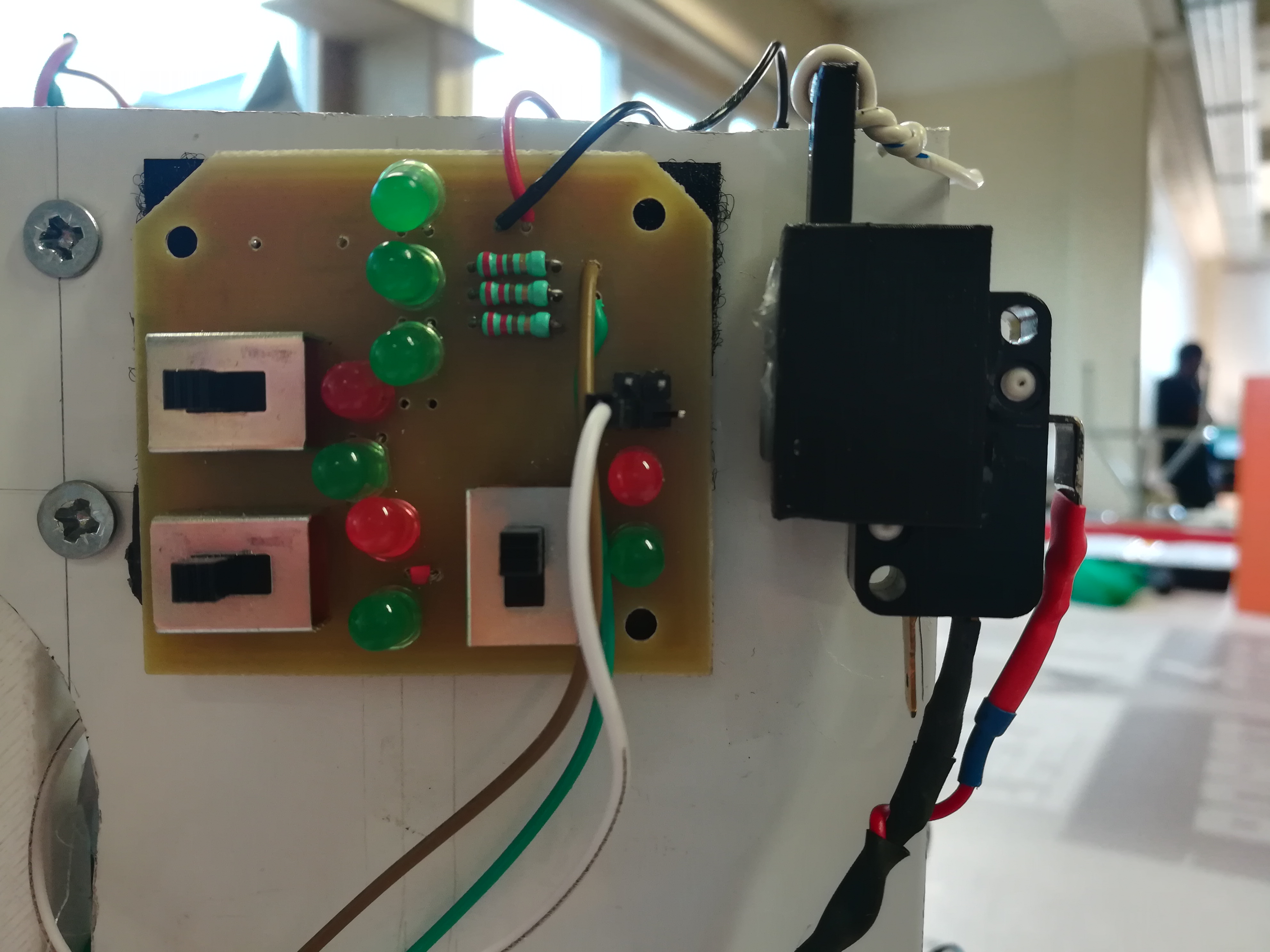
- The two couples of black and red wires are the 5V
- The white wire is connected to the pin 12 on the raspberry and send startup interrupt information
- The red point is the pin normally connected to the 23rd pin on the raspberry and send team switch information
- The brown and green wires are connected to the pins 21 and 20 on the raspberry and connect acknowledge pins
If you copied the code and connect all cable as the pictures shows, the pulling of the start cable induce a publication on the start ROS topic (visible with an echo on this topic) and the modification of the switch place sets the team parameter ROS file.
The switch strategy and initialisation were planned to respectively set a different implemented strategy and launch a initialisation (tests) sequence. It was not used in 2018 due to a lack of time but they are already on the PCB for a future robot.
Finally, in the real implementation on ROS, the pin configuration is placed in a .yaml file gathering all information required about raspberry pinout. Then, the code used to get pin number is
rospy.get_param("/path/name")
--- OneDrive link for Altium project
last updated on May 11, 2018
Motor Board
The goal of this board is to bring individual intelligence for every motor used on our robots. It allows to associate a microcontroller (ATmega328) with each motor. This main component is used for two aspects : regulation and communication.
Regulation
For the smaller robot, the operating system send speed consign to the four motors. Consequently, the goal for the motor is reaching this speed in a minimum of time and after conserving this value. The regulator implemented in the microcontrollers is Proportional Integral Derivative regulators. It's parameters allow to influence the way to consign reaching for the motor. Thanks to it, each motor, individually can follow the ROS order with a maximum of precision.
PID's parameters were found with experimentation and all sources used for implementation are in the code file.
Communication
As said in the previous part, this is the operating system ROS the main brain of the robot. Consequently, this brain has to communicate with its slave. The communication protocol used on our robots is SPI. It induces that a bus has to be built between all motor and ROS. Effectively, a broker gathers the signal for the motor but in any case each motor has to be linked to the bus. A role of the board is this connection via a SPI connector.
Getting Started
To simplify the tutorial, we will use an arduino UNO instead of ATmega328 microcontroller. For the robot, the reason why we use a ATmega328 alone is the size of the system. The microcontroller and its oscillator are sufficient for our application and take less place on the robot. However, in this tutorial, we will use the arduino UNO to slightly simplify manipulation.
Regarding the regulation, the following code implements the PID regulator. Its parameters were found after experimentation. It depends on the motor and the load. We simply adjusted the parameters until the motor behaviour was the expected one. (mr. Marchand knows the methodology ;) )
The blocks of the system are described below :
- Encoder
The encoder sends the rotation information to the controller. In our code, we used the Encoder.h library to handle it. At this moment, we have the velocity of the wheel in rad/s.
- Motor control
The H bridge is used for power two motors at the same. One the left side of the board there are all control pins (PWM and DIR for the two motors) and power supply of command (5V). On the other side of the board, you have the motor output and the motor power supply (24V).
#includes <Wire.h>
#includes <PID_v1.h>
#includes <ecamlib.h>

#include <Encoder.h>
#include <FlexiTimer2.h>

// Defines the pins to control the motor driver
// pin 5 controls the voltage to the motor by a PWM
// pin 4 controls the direction of the motor
const int PWM = 5;
const int DIR = 4;

// Define pin and tick per revolution of the encoder
Encoder motor_encoder = Encoder(2, 3);
const int ENCODER_TICKS_PER_REV = 3200;

// Defines the time between two samples in milliseconds for speed capture
const int CADENCE_MS = 50;
volatile double dt = CADENCE_MS / 1000.;

// Motor control variables and PID configuration
float motor_speed = 6.28319;
float gain_p = 15.0;
float gain_i = 5.0;
float gain_d = 0.5;

// Define angular velocity
volatile double omega;

// PID declaration function of used library
double Setpoint, Input, Output;
PID myPID(&Input, &Output, &Setpoint,gain_p,gain_i,gain_d, DIRECT);

// Variable to keep track of the old encoder value
volatile long old_encoder = 0;

void setup() {
    // set timer 0 divisor to 1 for PWM frequency of 62500.00 Hz
    TCCR0B = TCCR0B & B11111000 | B00000001;

    pinMode(PWM,OUTPUT);
    pinMode(DIR,OUTPUT);

 // Periodic execution of isrt() function thanks to FlexiTimer2 library
    FlexiTimer2::set(CADENCE_MS, 1/1000., isrt);
    FlexiTimer2::start();

    myPID.SetMode(AUTOMATIC);
    myPID.SetSampleTime(CADENCE_MS);

    // Motor direction
    digitalWrite(DIR,LOW);

}

void loop() {

 Setpoint = (double) (abs(motor_speed));
    if (motor_speed > 0) {
        digitalWrite(DIR, LOW);
    } else {
        digitalWrite(DIR, HIGH);
    }

    Input = abs(omega);

    myPID.Compute();

    analogWrite(PWM, Output);

    Serial.print("Omega : ");
    Serial.println(omega);
    delay(CADENCE_MS);
}

// Speed measurement
void isrt(){
    int deltaEncoder = motor_encoder.read() - old_encoder;
    old_encoder = motor_encoder.read();

    // Angular velocity
    omega = ( (2.0 * 3.141592 * (double)deltaEncoder) / ENCODER_TICKS_PER_REV ) / dt;  // rad/s
}
Remark : All used library is on Github (see link at the end)
- Controller
Motor are controlled by the arduino with PWM signals. The implemented PID regulator computes the necessary duty cycle to send for reaching the target velocity function of its parameters.
The following complete circuit is shown below
--- PIC OF THE CIRCUIT --- UNO + H Bridge + MOTOR - DRAW CONNECTION --- After robot's deconstruction
The implemented PID regulator computes to reach the target velocity. So at this moment, you have an arduino UNO controlling motor in velocity thanks to a PID regulation. All regulation is visible in the Serial Window of the Arduino software.
Now the next step is to give the control of the motor velocity to ROS core on the raspberry. For that, we implemented a SPI connection with ROS. These concepts are explained in the ROS serial section. On the motor side, a function is added on the main code on the arduino UNO to receive data from master and set value of PID (proportional gain, integrative gain, derivative gain and velocity setpoints.
// function that executes whenever data is received from the master
// this function is registered as an event, see setup()
void receiveEvent(int howMany) {
    if (Wire.available() >= 2) {
        unsigned char reg = Wire.read();

        switch (reg) {
            // Configuration
            case 0x00:
                Serial.println("Tried to change the configuration, but it's not handled yet...");
                break;

            // Set motor speed
            case 0x10:
                // Expecting a 4 byte float value representing
                // angular velocity
                if (Wire.available() >= 4) {
                    unsigned char b0 = Wire.read();
                    unsigned char b1 = Wire.read();
                    unsigned char b2 = Wire.read();
                    unsigned char b3 = Wire.read();
                    motor_speed = bytesToFloat(b0, b1, b2, b3);
                    Serial.print("Motor speed set to ");
                    Serial.print(motor_speed, 3);
                    Serial.println(" rad/s");
                }
                break;

            // Set PID gains
            case 0x20:
                // Expecting a 4 byte float value representing
                // proportional gain for the PID
                if (Wire.available() >= 4) {
                    unsigned char b0 = Wire.read();
                    unsigned char b1 = Wire.read();
                    unsigned char b2 = Wire.read();
                    unsigned char b3 = Wire.read();
                    gain_p = bytesToFloat(b0, b1, b2, b3);
                    Serial.print("Proportional gain set to ");
                    Serial.println(gain_p, 3);
                }
                break;
            case 0x21:
                // Expecting a 4 byte float value representing
                // integral gain for the PID
                if (Wire.available() >= 4) {
                    unsigned char b0 = Wire.read();
                    unsigned char b1 = Wire.read();
                    unsigned char b2 = Wire.read();
                    unsigned char b3 = Wire.read();
                    gain_i = bytesToFloat(b0, b1, b2, b3);
                    Serial.print("Integral gain set to ");
                    Serial.println(gain_i, 3);
                }
                break;
            case 0x22:
                // Expecting a 4 byte float value representing
                // derivative gain for the PID
                if (Wire.available() >= 4) {
                    unsigned char b0 = Wire.read();
                    unsigned char b1 = Wire.read();
                    unsigned char b2 = Wire.read();
                    unsigned char b3 = Wire.read();
                    gain_d = bytesToFloat(b0, b1, b2, b3);
                    Serial.print("Derivative gain set to ");
                    Serial.println(gain_d, 3);
                }
                break;

            default:
                Serial.println("Unexcpected register access over I2C");
                break;
        }
    }
}
Upload protocol for ATmega 328
If you understood the tutorial with arduino UNO and want to use the ATmega328, you just have to use PCB with connection show below and implement the code exposed above on the ATmega328. This mocrocontroller is programmed with the ISP Programmer explains in the relative section.
--- PIC OF THE CIRCUIT --- Motor board + H Bridge + MOTOR - DRAW CONNECTION --- After robot's deconstruction
--- OneDrive link for Altium project
Arduino Communication Shield - SPI Broker
last updated on May 11, 2018
Motor command communication consists of a two-level interface. ROS communicate via ROS Serial (explained in the appropriate section) implemented on an arduino UNO and this arduino handle the communication with the four individual motors. To help for connections, we designed an arduino shield gathering simply all SPI bus connections. The only role of the PCB is deleting redundancy in the SPI bus connections and consequently facilitating the SPI bus execution. As the PCB is really simple, it implements a bus SPI connection, it requires no explanation.
The utility of this PCB concerns SPI and Ros Serial, you will find more explanation about these subjects in the related section.
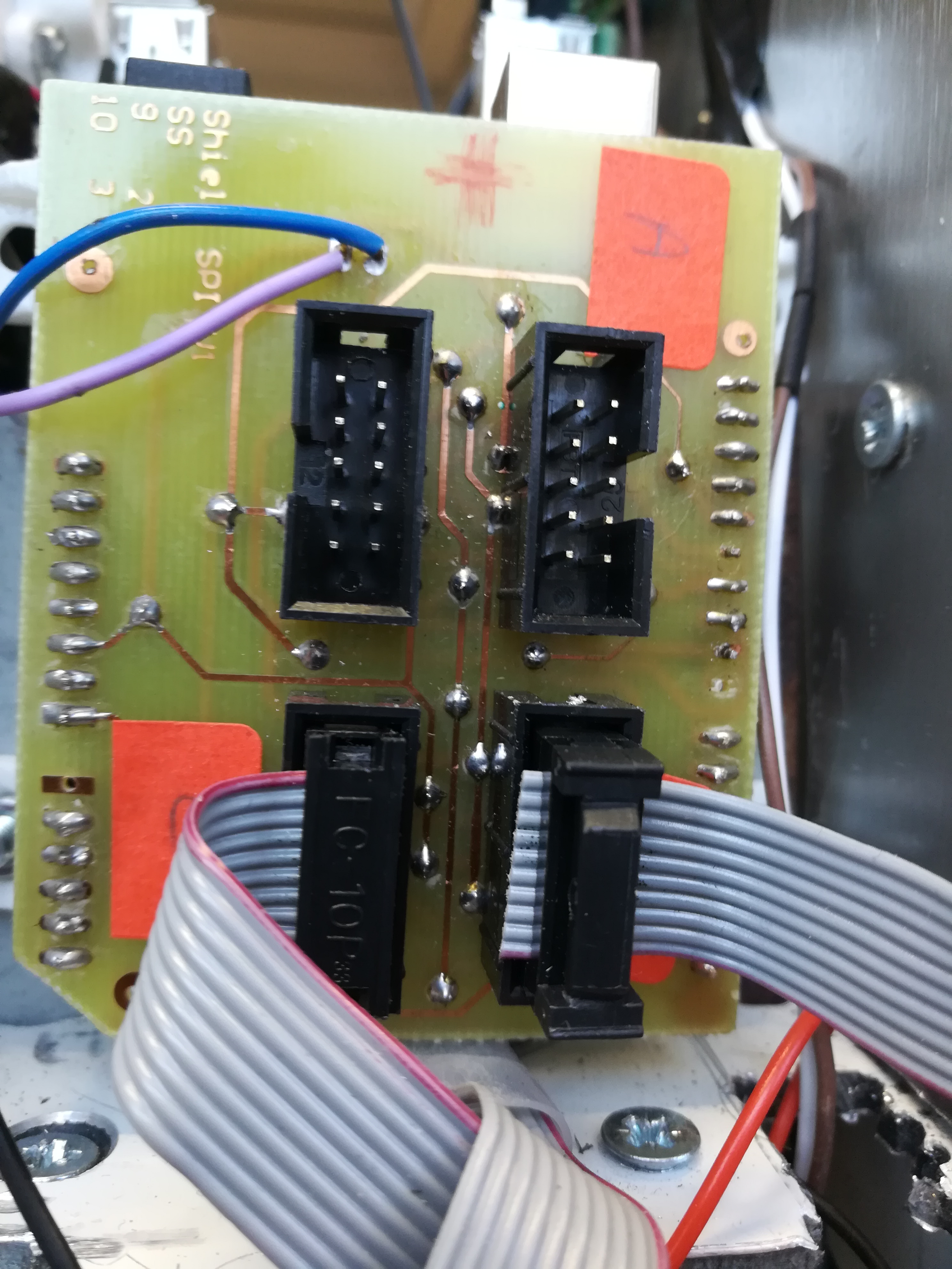
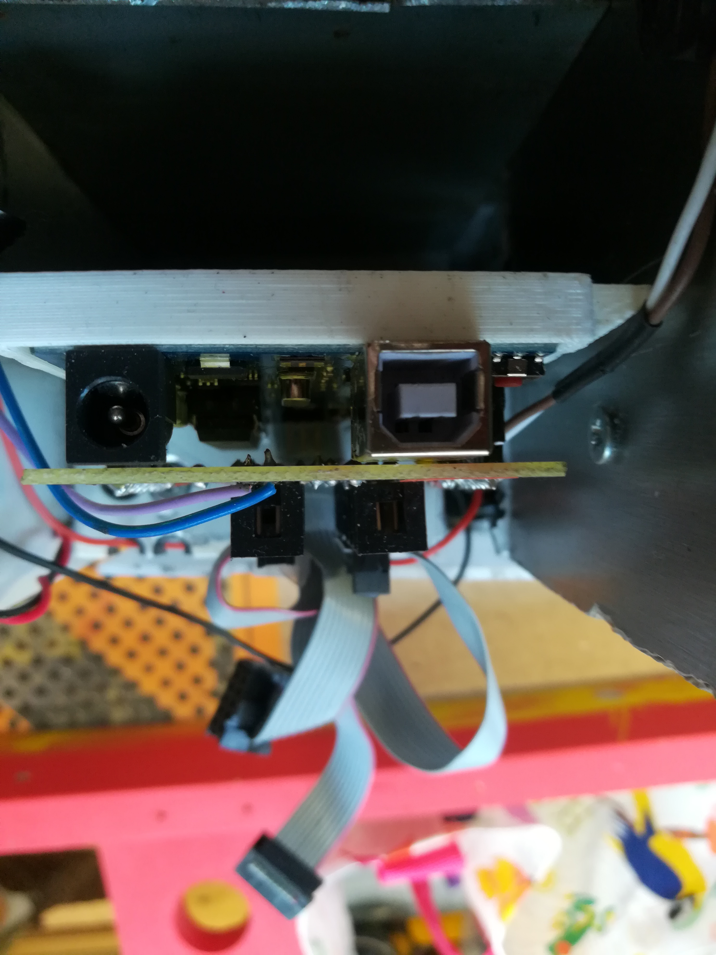
--- OneDrive link for Altium project
Power supply board
This PCB is consisted of six pieces of DC-DC Power Supply Adjustable Step Down Module with an adjustable potentiometer to fix the value of the voltage wanted (24V 12V 9V 5V 3V).

Those are Mini MP1584EN DC DC buck converter step-down module with a wide range of:
• Input voltage: 4.5V to 28V
• Output voltage: 0.8 V to 20 V
• Output current: 3 (maximum)
•  Conversion efficiency: 92% (maximum)
• Output ripple: less than 30 mV
• Switching frequency: 1.5 MHz (higher), usually 1 MHz
• Operating temperature: -45 ℃ to 85 ℃;
• Size: 22 mm by 17 mm by 4 mm

Warning:
• Do not reverse the positive and negative terminals to avoid possible damage.
• Do not use a light load (less than 10% power output) or no load

The Purpose of the creation of this board is to realize a better power supply board by:
• Gathering all those 6 pieces on one board with different output voltage
 • Rearranging their outputs in such a way the + and the – become side by side so it is easier to be plugged by the user. Also creating an USB port output for the Arduino.
• Adding protection to the Board using fuses at the entrance of each PCB (the fuses must be with different values depending on the value putted on the potentiometer).
• Rearranging their outputs in such a way the + and the – become side by side so it is easier to be plugged by the user. Also creating an USB port output for the Arduino.
• Adding protection to the Board using fuses at the entrance of each PCB (the fuses must be with different values depending on the value putted on the potentiometer).

3D PCB

This is the final power supply board with its new outputs including USB port output and its protection:

IMPROVEMENT
For better protection to our power supply board we can improve our protection by adding a freewheeling diode to protect the board in case the battery terminals are inverted.
If we had to redo it
last updated on May 11, 2018
If we had to design another robot with technologies described, there are some decision that we would change.
- PCB Design
The ECAM installation for PCB printing is very useful for prototyping. It is not comparable with PCB that specialised company can create. So, our advice is the following, as soon as a board is functional and definitive, send it to have a proper and reliable board. Moreover, try to reach this step as soon as possible.
- Connection
We have underestimated the connection on the different board. Regarding the JST connector, they are solid but hard to disconnect and cable creation is long without the right tool. About the 10 pins shrouded header, they are not reliable enough. Opposite to the JST, disconnection is too easy. We really advise against its use. They were the source of a lot of problems. About the SPI connector (10 pins shrouded header) it was not strong enough. The contact failure brought a lot of problems in the communication between ROS serial and ATmega.
In the two situations, we advise against the use of these two types of connector, there are a lot of alternative solutions.
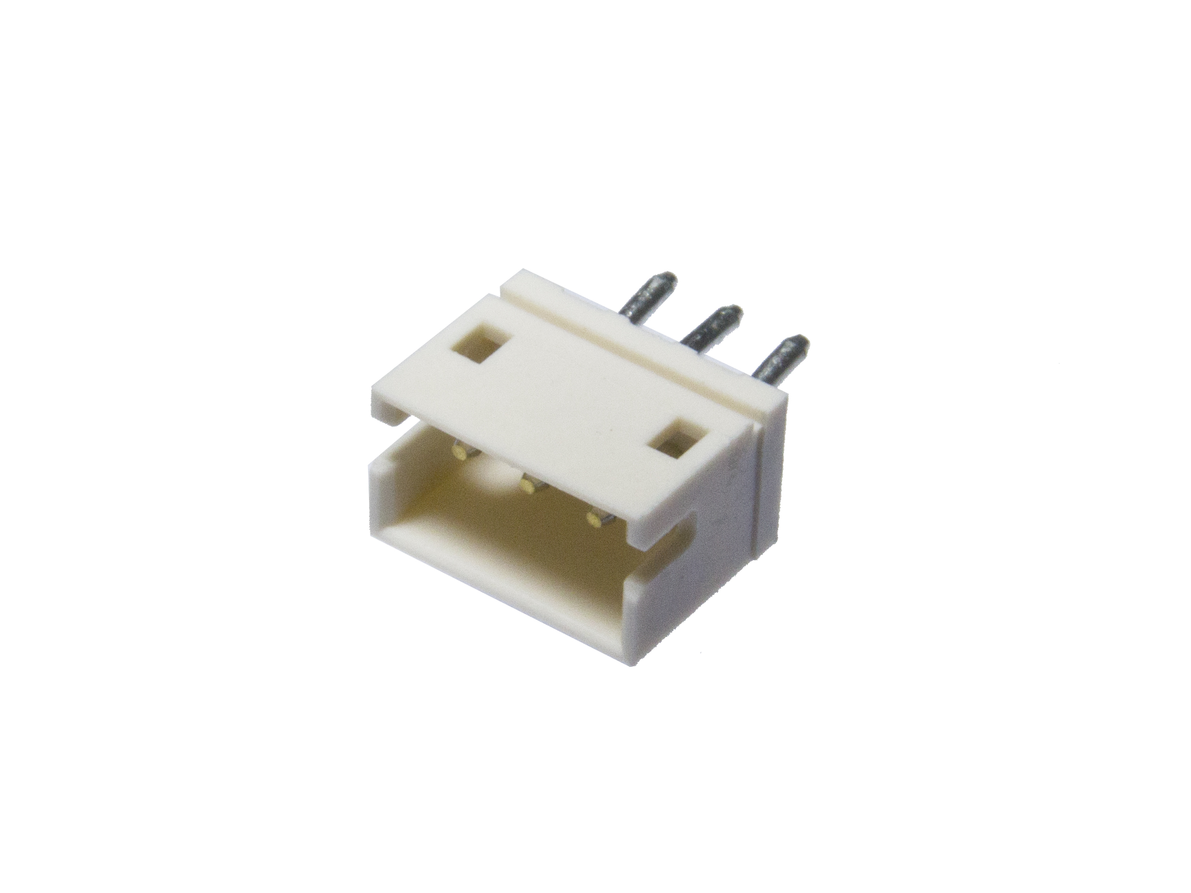
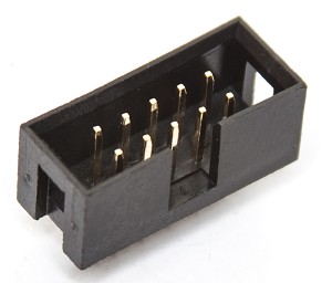
FPGA
A. FPGA
1.FPGA: What is it?
Field Programmable Gate Array - Programmable Gate System These are programmable (or rather reconfigurable) integrated circuits many times and more and more dynamically! They allow Either to simulate a circuit to validate it before silicon etching Either to implement a complete system, System on Chip (SoC) By using dynamic reconfiguration, this system can become adaptive as needed (acceleration of selected features).
1.1. Introduction:###
FPGAs consist of a matrix of programmable logic blocks surrounded by programmable output input blocks. The whole is connected by a programmable interconnection network. FPGAs are distinct from other programmable circuit families while offering the highest level of logical integration.
There are 4 main categories available commercially:
Symmetrical table. In column. Seas of doors. Hierarchical PLDs.

1.2.FPGA structure
The specifications of an FPGA often include the number of configurable logic blocks, the number of logic blocks of frozen functions such as multipliers and the size of the memory resources such as the embedded RAM block. An FPGA integrated circuit is composed of several other elements, but these are typically the most important when it comes to choosing and comparing FPGAs for a specific application.
Configurable logic blocks (CLBs) are the basic logical unit of an FPGA. Sometimes called "slices" or "logical cells", logical blocks consist of two parts: flip-flops and correspondence tables (LUTs). The way flip-flops and LUT lookup tables are assembled differs depending on the types of FPGAs, so it's important to understand their features.

1.3.The Possibilities
With an FPGA you are able to create the actual circuit, so it is up to you to decide what pins the serial port connects to. That also means you can create as many serial ports as you want. The only limitations you really have are the number of physical I/O pins and the size of the FPGA. Just like microcontrollers that have a set amount of memory for your program, FPGAs can only emulate a circuit so large. One of the very interesting things about FPGAs is that while you are designing the hardware, you can design the hardware to be a processor that you then can write software for! In fact, companies that design digital circuits, like Intel or nVidia, often use FPGAs to prototype their chips before creating them.
FPGA continues to dominate as the evolution of high-level tools allows engineers and scientists to enjoy the benefits of reprogrammable circuits, regardless of their level of experience. For more information on using FPGAs in different industries and applications
B.SPI
1 INTRODUCTION
The protocol that we will use is called Serial Peripheral Interface (SPI). It is a synchronous full-duplex serial interface and is commonly used to communicate with on-board peripherals such as EEPROM, FLASH memory, A/D converters, temperature sensors, or in our case a Field Programmable Gate Array (FPGA). We assume a working knowledge of the VHDL hardware description language.
2 HARDWARE
SPI is a protocol, in which one device (the master) controls one or more other devices (the slaves). For the master we use an open-source microcontroller prototyping platform, such as the Arduino 101 or a modified Arduino UNO R3. In this document we use Arduino to refer to either platform. The slave can be a low-cost FPGA prototyping platforms, such as the Xilinx Spartan-6 Avnet LX9 or the Altera Cyclone-IV Terasic DE10-Lite . The repository includes project files and pin assignments for both these boards. The code is written in VHDL and should work equally well on more powerful boards.
2.1.Voltage levels
It is very important that the I/O voltage levels of the devices match. Both FPGA boards support 3.3V levels, and are a good match for the Arduino 101. However, the Arduino UNO uses the traditional 5 Volt TTL levels. Instead of using a level shifter, such as the 74LVC245, we opt for converting the Arduino to 3.3V according to Adafruit’s instructions. Running a 16 MHz clock at 3.3V is out of spec. Is said to work, but should really program the fuses to get the frequency down to abt. 13 MHz .
2.2.Signals
The SPI interface is a 4 wire interface. The bus consists of 3 signals plus a slave select signal for each device.
SCLK: clock signal sent from the master to all slaves.
MOSI: serial data from the master to the slaves (Master Out-Slave In).
MISO: serial data from a slave to the master (Master In-Slave Out).
SS: slave select signal for each slave.
Once the Arduino runs at 3.3V, connecting the two devices becomes trivial.
2.2.1. Pin outs
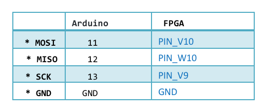
2.2.2. The physical connections
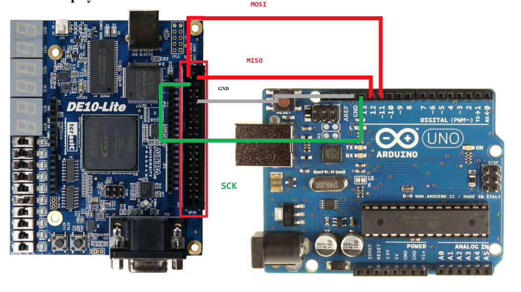
3. BYTE – PROTOCOL
With the two devices physically connected, we need a protocol to transfer data. We chose the Serial Peripheral Interface (SPI), a lightweight protocol to connect one master to one or more slaves.
3.1 Master/slave
The SPI bus is controlled by a master device (typically a microcontroller) that orchestrates the bus access. The master generates the control signals and regulates the data flow. The illustration below shows a master with three slaves. The master uses the Slave Select (SS) signal to select the slave.
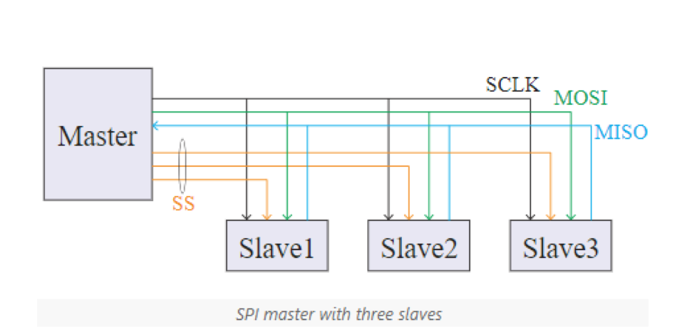
3.2 Parameters
SPI is also a protocol with many degrees of freedom. It is important that the master and slave agree on the voltage levels and maximum clock frequency. The SPI clock polarity (CPOL) and clock phase (CPHA) introduce four more degrees of freedom as shown in the table below. SPI parameters
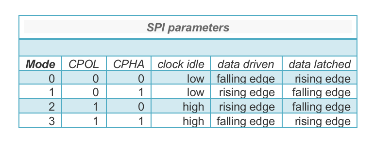
For this article we assume mode 3, where the clock is high when idle; data is driving following the falling edge of the clock and latched on the rising edge.
3.3. Operation
The protocol is easiest explained with shift registers as shown in the illustration below. The master generates the SPI Clock (SCLK) to initiate the information exchange. Data is shifted on one edge of this clock and is sampled on the opposite edge when the data is stable.
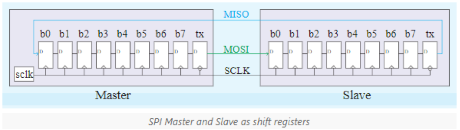
In mode 3, at the falling edge of SCLK, both devices drive their most significant bit (b7) on their outgoing data line. On the rising edge, both devices clock in this bit into the least significant bit position (b0). After eight SCLK cycles, the master and slave have exchanged their values and each device processes the data received (e.g. writing it to memory). In case there is more data to be exchanged, the registers are loaded with new data and the process repeats itself. Once all data is transmitted, the master stops the SCLK clock.
3.4. Slave select
For a more complete picture, we need to include the effect of the slave select (SS*) signal that is used to address the slave devices.
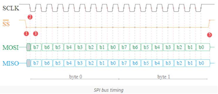
Slaves may only drive their output (MISO) line when SS* is active, otherwise they should tri-stated the output. The protocol can be broken down into the following steps:
-
The master initiates the communication by activating SS*
- The slave responds by starting to drive its MISO output.
-
Meanwhile the master drives its MOSI output.
-
The master makes SCLK low.
-
On this falling edge, the master and slave drive their most significant bit position (b7) on respectively their MOSI and MISO outputs.
-
The master makes SCLK high.
-
On this rising edge, the master and slave clock the input from their respectively MISO and MOSI inputs into the least significant bit position (b0).
-
Go back to step 2. Until the least significant bit position (b0) has been sent.
-
When all bits are transmitted, the master deactivates SS*.
4. BYTES EXCHANGE WITH ARDUINO AS MASTER
The Arduino is blessed with a support library for the serial peripheral interface. This greatly aids the implementation. For the slave we used an Altera or Xilinx based FPGA implementation . Refer to the first part of this article for details about the physical connection.
5. BYTE EXCHANGE WITH A FPGA AS SLAVE
Implementing the SPI Slave on an FPGA is like old school digital electronics. My key takeaway is to think hardware, not programming. Implementing the SPI protocol on a FPGA is fairly straightforward for as long as we use a directly clocked sequential circuit while preventing clock domain crossings.
5.1. Sequential circuit
In real life, two signals going to a single gate will not arrive there at the same time due to wire delays. This causes the output to momentarily have an incorrect value. The problem compounds as the signal travels through more gates and wires.
In Building Math Hardware we created elementary math operations using combinatorial circuits. That was OK, because we didn’t care about such output glitches caused by the input signals propagating to the outputs. From a demonstrator’s point of view it even made it more interesting. Talking to a real device, such as a SPI master is different, because it requires the outputs to be stable at certain times.
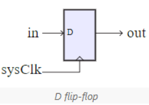
The solution is to introduce a clock signal, and store the signals in a flip-flop (registers) at the rising edge of that clock signal. We then only need to ensure that the longest delay from one flip-flop to the next is less that the clock period. This greatly simplifies the design process, at the cost of introducing some delay.
5.2. Clock domain
Field programmable gate arrays thrive on synchronous designs, but they don’t do well with clock signals that are asynchronous with its system clock.
We also need to avoid transferring data from a flip-flop driven by one clock to a flip-flop driven by another clock. This is called a clock domain crossing and might manifest itself in metastability, data loss or incoherence .We prevent clock domain crossings, by synchronizing the input signals to the FPGA clock using a traditional two-stage shift register as illustrated above.
-
The first flip-flop creates a synchronous version of the inputs by clocking it with the system clock. The input signal could change within the flip-flop’s setup and hold times and may take longer than a system clock cycle to settle to a stable value (metastability). That’s why it is ran through a second flip-flop.
-
The second flip-flop, makes it is very unlikely that this metastability propagates to the output.
-
Adding a third flip-flop gives us access to the previous value. Using the current and previous values, we can generate rise and fall signals as sown below.
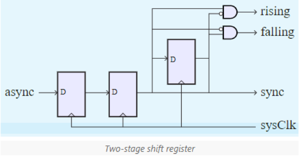
5.3. Operation
The main data object is an 8-bit register called DATA.
On a falling SCLK edge, the most significant bit from data is clocked into a register from where it is transmitted over its MISO output.
On a rising SCLK edge, the MOSI input is shifted into the least significant bit of data.
Once all eight bits are received, the byte is available as rx. This received byte rx should be read when rx Valid is active during a rising edge of the sysClk.
6. MESSAGE EXCHANGE PROTOCOL
The time has come to implement a status and register interface on top of the raw byte exchange. We define a few commands to retrieve the device status and access its 32-bit registers.
6.1. Commands
The first byte is defined as the command byte. The interpretation of the remaining bytes (if any) depends on this command. After the command is completed, a new command can be sent. The following commands will be supported:
- Read status (0x00): Reads the status byte.
First the master sends 0x00, and ignores the value returned;
the master then sends one dummy byte, to get the 8-bit status value in return.
- Read register (0x80 to 0x8F): Reads the value stored in one of the sixteen registers.
The least significant four bits of the command indicate the register to read from. First the master sends this command, and ignores the value returned,then the master sends 4 dummy bytes to get the 32-bit register value. The first byte received is the most significant, the fourth is the least significant (network byte order).
-
Write register (0xC0 to 0xCF): Writes a value to one of the sixteen registers. The least significant four bits indicate the register to write to.
- First the master sends the command, and ignores the value returned;
- Then the master sends 4 bytes with the value to write. The most significant byte is sent first, the least significant last.
6.2. Registers
The FPGA will implement two register types. The first 4 registers (0-3) are read/write and can be used to send information to the FPGA. The next 12 registers (4-15) are read-only to receive information from the FPGA. In the greater scheme, the read/write registers will be used to send math operands to the FPGA, and the read-only registers will be used to read the results from the FPGA.
6.3. Room for improvement
The protocol leaves some room for improvement. It can be made more efficient by implementing continuous commands. Here the master issues a read or write register start command, but keeps sending sets of 4-bytes until it has enough. Along similar lines one could implement commands to access attached memory.
7. MESSAGES EXCHANGE WITH ARDUINO AS MASTER
Again, we’ll use the support library for the serial peripheral interface. The code shown below was tested on a 3.3 Volt Arduino UNO R3 connected to FPGA implementation.
This section aims to show how different communication techniques have been implemented
I2C
last updated on May 10, 2018
The 2017 team had some problems with this bus of data. After some tests, we decided not to use the I2C as a our communication system. Maybe next year ...
Serial Peripheral Interface (SPI)
last updated on May 10, 2018
Quick theoretical reminders
The Serial Peripheral Interface bus (SPI) is a synchronous serial communication interface specification used for short distance communication, primarily in embedded systems.
You can see on the picture below the topology of this communictaion interface and the pinout of the components:

SPI only defines the physical and data link layer of OSI network model. The connection and media between the devices indicates the physical layer. Data link layer defines the way in which the devices are connected. The connections include the input and output lines such as clock, data in and data out. Data link layer in SPI is implied in the connection itself and no provision is made for location or address information.
The communiction frame is writen for the use (Layer three on OSI Model). To begin a communication with a Slave, the Master must fix the Slave Select pin (SS) to LOW state. After that, the master can put some bits into the shift register throught the MOSI (Master Output Slave Input) pin. When the communication is done, it's the master who must put back the SS to HIGH State.
Note : It's a full duplex interface, The slave can push some data on his MISO (Master Input Slave Output) pin during the communication.
![]()
advantages
- Full duplex communication
- Flexibility of the number of bits to be transmitted as well as the protocol itself
- no possible collision
disadvantage
- (3 + N*Slaves) pins are required on the master
- 4 pins are required on each slaves
- Master can speak in a vacuum without knowing it
- Bus can only count one master
Use of our SPI
the communication frame we used to send data to the slave is:
- Register adress on 8 bits
- Number of bytes composing the message
- Message
Note : to read some data from a slave's register, the master must just send the register adress. The slave push the data on his MISO (Master Input Slave Output) pin.
Our Master
Create a SPI Master is really easy with a atmega328p and the arduino IDE. Indeed, we can find easily some libraries. We used the one provided directly by the arduino IDE in an object that we implemented : SPIManager
how to work with SPIManager object will be illustrated at least code use for Cortex's engines control (Eurobot 2018) : MotorBroker
1. Initialisation of the SPI communication
The SPIManager object must be seen as a communication channel with the slave. It will be necessary to instantiate one SPIManager object by slave. When creating the object, use the number of the SS pin as an argument.
//Define the SS pin for each slave
#define FL_SS  9
#define FR_SS  2
#define BL_SS  10
#define BR_SS  3

//Object Instantiation
SPIManager connFL(FL_SS);
SPIManager connFR(FR_SS);
SPIManager connBL(BL_SS);
SPIManager connBR(BR_SS);
Use the initialize() method to activate the communication channel. This call should be placed in the setup() function of the arduino code.
connFL.initialize();
2. Write data to a Slave's register
as said above, to write a value in a register of the slave will first send the address of the register, then the size in number of byte and to finish, the message.
The writedata function has been written to make its use as intuitive as possible. below, an example of use where we send to the register 16 (0x10), the message x.b whose size is 4 bytes.
connBR.writeData(0x10, 0x04, x.b);
3. Read data from a Slave's register
There are two functions to read some data: the first,readLongData , will return a value of type long and the other ,readData , a value of type float32
below, an example of use where we get some data from th register 81 (0x51).
encoders_msg.rear_left = connBL.readLongData(0x51);
Our Slaves
When using the Arduino IDE to program atmeg328p, the slave mode is not available. Two registers must be modified to activate this mode :
// turn on SPI in slave mode
SPCR |= _BV(SPE);
// turn on interrupts
SPCR |= _BV(SPIE);
So that these manipulations are transparent for the user we also create an object for the SPI bus slaves : SPISlave
this object has several methods :
- begin() : change the two registers cited above and declaring the MISO pin as an output.
- reset() : reset private object variables.
- com(): manage the communication by putting the incoming data in the right variables.
and some properties :
- command : return the register address.
- dataSize : return the size of the incoming message.
- msg : return the message (maximum 64 bits).
- endtrans : boolean that returns true if communication is complete.
1. Initialisation of the SPI communication
The MOSI, MISO and SLK pin are always the same on arduino. If you want you can change the SS pin number we agree to use pin 10 as pin SS for the slave.
Note : SS is a reserved name used for the SPI communication.
On the begin of our script we create a SPI object and define the SS pin number as it's done in the following code :
SpiSlave mySPI;

//SLK  : pin 13
//MISO : pin 12
//MOSI : pin 11
#define SS 10
to enable the communication, use the begin() method of the SPISlave object in the setup() function of the atemega :
void setup()
{
    mySPI.begin();
}
2. Interruption
An incoming call performed by the master to the slave triggers an interrupt. In most cases, the method in which the interrupt routine will be placed will be: ISR (name _of _a _register). in our case the register will be SPI _VTC _vect. As we work whith an atemega328p the shift register is called : SPDR.
This way of working is illustrated in the following code :
//Interrupt needed by SPI Communication
ISR (SPI_STC_vect) {
    //manage the communication by putting the incoming data in the right variables.
    mySPI.com(SPDR);
    //Method containing the registers of the Slave.
    spiReg();
}
3. Registers
A SWITCH is commonly used to define the registers. In our case of use, it is the command property of the SPISlave object which is used as parameter of the SWITCH.
the writing in a register will be done once the communication is finished (thanks to the property endTrans). This method of work has the advantage of not having inconsistent values during the communication.
The reading of a registers uses the full-duplex channel provided by the SPI. The data are pushed through the channel during the communication using the SPDR register.
Here is an example of a function that contains the registers of a slave:
void spiReg(){
switch (mySPI.command) {
  case 0x10:
      if(mySPI.endTrans) {
          for (int i = 0; i < 4; i++){
              motor_speed.b[i] = mySPI.msg[i];
           }
       }
      break;
   case 0x11:
      SPDR = motor_speed.b[mySPI.dataCount - 2];
      break;
   case 0x50:
      motor_encoder.write(0);
      break;
   case 0x51:
      SPDR = EncoderState.b[mySPI.dataCount - 2];
      break;
  }
}
Troubleshooting
Patched but not fixed
1. Problem between serial port (ROSSERIAL) and SPI bus
There is a competition between Rosserial and the SPI since both use the serial bus. when one ROS sends a data via the serial port, the communication SPI is interrupted.
Patch : simply initialize the SPI communication before each data transfer
void message_to_FR( const std_msgs::Float32 & toggle_msg){
    x.val = toggle_msg.data;
    connFR.initialize();
    connFR.writeData(0x10, 0x04, x.b);
}
2. sometimes the slave update the value of a register with the value received previously
we observed that sometimes the received data are updated with a delay of ONE communication. The problem is that if the time between two communications is long, there will be latency before the update in the registry.
Patch : The data is sent by ROS every 50ms even if it is not changed (see on motor_sim.py)
3. Changing the values of a register when reading another register
When we want to read the return of a slave encoder we send a series of null bytes after the address byte to receive the value. But these null values are misinterpreted and the engine speed drops to zero. Probably from a coding error.
Patch : We send velocity value instead of null bytes. (just using during the Eurobot sprint)
Just for curious.
https://github.com/Sellto/SPIandROS_HelloWord
Three simples scripts to train you with ours SPI objects and with or without rosserial communication.
Decription of the situation :
- The two slaves has a LED connected to pin 4 whose state is modifiable by a SPI register.
- The master is connected to ROS which controls the flashing speed of each led.
Video-Tuto : ASAP
References
https://en.wikipedia.org/wiki/Serial_Peripheral_Interface_Bus
Why using CANBus on the robots and how to implement it
Issues and context of the Eurobot ( 2018 )
Many technologies have been implemented on the robots for the 2018 edition of the EUROBOT.
Those technologies were a huge step forward in terms of quality, speed and ease of use.
However, unexpected downsides appeared during the implementation of the technologies on the robots.
Thoses downsides are of all type but those who are speaking about during this tutorial are *electronic and space.

Electronic problem
Once the boards are installend on the robots, they needed a lot of connections between them. The last picture shows the kind of result we got after connecting all the wires.
From that moment it is very complex to add or remove wires because of the big amount of cables.
It is also very complex for the debugging because it is hard to take measures and to find where the error is.
Space problem
Another problem wich appeared and that we didn't is the huge space taken by the wires.
During the conception the mistake we did is to disregard the size of the wires. In the future, some leeway should be taken on the size of the robot during the conception.
The huge number of wires had also an mechanical impact. It added constraint on the connexions wich often broke.
Le CANBus
Context
Those problems have already been met many years ago in the automotive. Indeed, more and more electronic devises were used in the cars for differents purposes :
- Engine temperature, air...
- RPM, speed...
- accelerometer...
- Safety, ABS, Airbag, opened doors, seatbelt...
Specifications
We can cleary see that with the number of wires increasing the wiring harness became a real problem.
To resolve this, BOSCH developped the CANBus with several caracteristics :
- High speed communication up to 1 Megabit/s (see the table below for more information)
- Real time ( wich makes CANBus better than TCP/IP)
- Error detection, fast recovery and repair ( stil in real time)
- Security and stability
- Priorization of transmission
- Based on a differiental signal, the CANBus is made for harsh environnements (External noises and fault tolerance)
- It uses a twisted pair cable wich limits the noise emition
You can see below the speed transmission according to the distances
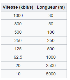
Topology
Finally, the biggest benefit of the CANBus is his one bus line topology which limits the number of cables to 4. (CAN HIGH, CAN LOW, VCC and GROUND).
This the reason why it is used on every modern car.
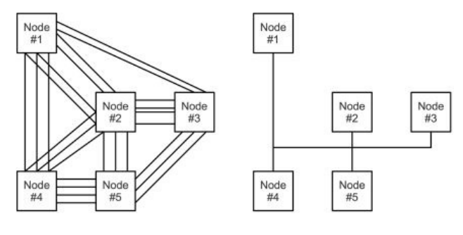
We can see on the last figure a system without the CANBus (left) and a system with the CANBus (right).
Every component, called a node, is connected to the bus line like the figure below :
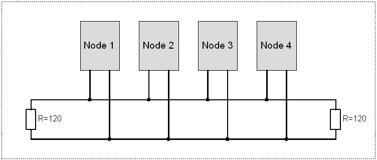
By analogy, the CANBus can be represented by a number of people ( the nodes ) in a room ( the bus line ) where everybody screams his informations. Everyelse has the choice to listen or not. A priority system chooses who is going to speak when several people want to speak at the same time.
The frame
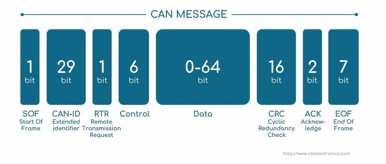
A data frame is made of different parts :
- 1 dominant bit begins the frame
- The ID of the message is made of 11 bits in the standart CAN or 29 bits in the extended CAN.
- 6 bits which determine the lenght of the frame
- The data made of 0...8 bytes
- 15 bits of CRC to detect errors
- ACK
- End of frame bit
Priority of transmission
When differents nodes whant to talk at the same time on the bus line, it is the ID who is going to determine the priority.
It gives an important advantage to CANBus, it is possible to make priority of transmission by choosing the right ID. For example, in car the brake system is more important than the light system. The ID of the brake system will be lower ( more 0 ) than the light system.
Implementation
Hardware
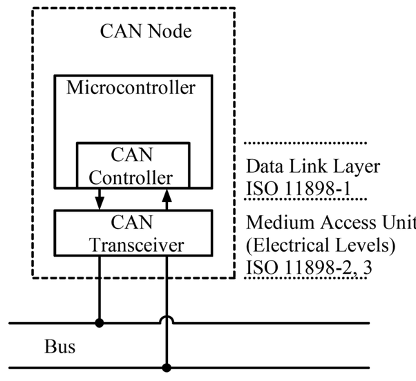
The last figure shows the implementation of the CANBus. The implementation is quite easy because of the modules proposed by Microchip.
A node is made of a transceiver, a CAN controller and a microcontroller.
Transceiver
Microchip proposes a lot of solutions for the automotive including a transceiver.
It is the MCP2562. Formerly the MCP2551, is used to convert the TTL signal to a differential signal required by the CANBus.
Controller
Microchip also proposes the CAN controller MCP2515 which implements all the CAN 2.0 specifications. It is able to send and receive data and communicate it via SPI to a microcontroller.
Microcontroller.
Any microcontroller with an integrated SPI communication can be selected.
For example we can take the famous ATMEGA328p known for his arduino IDE.
Resistance
In every communication wire there is some reflexion that can corrupt the data. It can be avoided by using 120 Ohm resistor at the end of line.
PCB
Coming soon.
Software (Arduino)
There are many libraries that propose functions to interract with the CAN controller via SPI from the micrcontroller.
A very comlete and up to date library is the Seed studio lib : https://github.com/Seeed-Studio/CAN_BUS_Shield
Filters
Filters allow to choose wich messages will be sent to the microcontroller from the CAN controller.
The MCP2515 is able the define 6 filters. For example :
CAN.init_Filt(0, 0, 0x04);
CAN.init_Filt(1, 0, 0x05);
This code means that the CAN controller will only listen to the messages with an ID of 0x04 and 0x05.
Masks
The masks defines the bits that will be inspected to filter the coming ID. If the bit of the mask is 1, it means that the ID has to respect the bit of the filter.
For example with the following filter :
0100 1101
If the mask is :
1111 1111
Then it means that the accepted ID has to have exactly the same bits thant the filter because all the masks bits are 1. Only a message witch the next ID will be accepted :
0100 1101
Now, if the mask is this one :
1111 1110
It means that the filter will not inspect the last bit of the ID.
The next ID's will be accpeted
0100 1100
0100 1101
Usefull links
- Introduction to CANBus by Texas Instrument, http://www.ti.com/lit/an/sloa101b/sloa101b.pdf
- CAN specs by BOSCH, https://www.kvaser.com/software/7330130980914/V1/can2spec.pdf
- CANBus implementation with Arduino, http://www.prometec.net/wp-content/uploads/2015/07/Controller-Area-Network-Prototyping-With-Arduino-Wilfried-Voss.pdf
- Well documented on Wikipedia, https://en.wikipedia.org/wiki/CAN_bus
Software
The software is an important part of the Robot. It is often the one that is the most challenging as to few people work on it. In this part, we are going to introduce you to the software stack of our robots. We will present the different technologies we used and try to explain many of the concepts related to them.
In 2018, we build the robots around ROS, which is a robotics framework facilitating software development for robotics. ROS is not easy to start with, but once you get the hang of it, it greatly improves your productivity. In the ROS chapters, we will try to distill the most important information in order to get you started quickly.
Install docker
To ease the development process, we recommend installing ROS inside a docker container instead of using a virtual machine. This comes with several advantages like ease of installation, having a common development environment and performance gains while compiling and running code on your computer.
It is important to note that the robot will not use docker and will run ROS packages natively. If you are an expert and know what you are doing, feel free to use your own method to develop ROS packages. Be it inside a virtual machine or a dedicated linux partition on your drive. Otherwise, just stick to the instructions below.
Linux
The installation varies quite a bit depending on the distribution you are using because the repositories are different for each distribution. For more information, visit this link and choose your distribution. If your distribution is not listed, try looking at the documentation of your own distribution.
Windows
On windows, you can download and install this executable. Once the docker app is installed, run it and you should see the docker icon in your system tray. Always make sure the service is up and running before trying to do anything with it.
For more information, follow this link.
macOS
Download and run this image. When asked, drag and drop the docker.app whale icon to the application folder. Once it is finished, simply start the docker service by running the docker app. You should see the docker icon in your system tray. Always make sure the service is up and running before trying to do anything with it.
For more information, follow this link.
Download the ROS container
Once docker is properly installed and the service is running, we can download the ROS image.
To begin, open a terminal (or docker cmd on windows) and enter the following command: docker pull ros
This will start the download of the official ROS image from the docker hub.
Run the container
When all of the files have been downloaded, run the container with the following command:
docker run -it --name=robot ros.
This command does several things. First of all, docker run creates a new container based on the ROS image we just downloaded and starts it. The -it parameter spins up an interactive bash shell inside the container and attaches it to the current terminal. Finally, the --name=robot renames the container to something easy we can work with later. You can give this any name you'd like.
You now have a functionning ROS environment.
To exit the container, use ctrl + d or type exit in the terminal.
Now, if we want to get back into the container we were just using, we can't use the same command as above as it will again create a new container just like before and all our modifications would be lost.
Instead we need to start the previous container again and attach to it. This can be done with the following command:
docker start robot && docker attach robot
The && tells our shell to execute the second command once the first one completed successfully.
You should now be back into the bash shell inside the container.
To start working on ROS projects, we recommend creating an appropriate workspace inside the /home/ros directory like so:
mkdir -p /home/ros && cd /home/ros
You can now follow the instructions to setup your workspace.
Additional notes
Run multiple shells inside the container
By default, only one bash session is running inside the container. Practically, this means that if you try to attach the same container in multiple terminals simultaneously, you won't be able to run separate commands in each.
To fix this -- and this will be needed to launch roscore in background before any other ROS command -- start a new bash session inside the container by typing the following in a new terminal:
docker exec -it robot bash
This will start a new bash session inside the already running container and attach to it automatically. If you exit this session, the container will keep running in the background. To stop the container, you will have to exit from the terminal where you started (or attached) to it. You can also stop a container with the command docker stop robot.
ROS
ROS or Robot Operating Systems is an open source framework designed for designing robots. ROS is commonly installed upon a Linux operating system. There are different ROS versions:
- Lunar (Latest)
- Kinetic (LTS)
- Jade
- Indigo
- ...
The ROS distribution we're using for Eurobot is the 'Kinetic' versions.
What's great about ROS, it's that there is an ever growing community that is sharing their code & projects of robotic machines. This is great because there are many build-in/downloadable libraries ready to use and the end user doesn't need to reinvent the wheel for classic robotic manipulations, like for example:
- Drivers to read/write to sensors
- Robotic algorithms (navigation, interpret sensor data, object manipulation)
- ...
In this section we will go over the basic concepts of ROS, the actual installation and the realisation of a project from scratch.
Installing ROS
ROS is only officially supported on Ubuntu or Debian, with other platforms being experimental or unofficial. We recommend installing Ubuntu for desktops or laptops and Ubuntu Mate for the Raspberry Pi.
Installing ROS on a Raspberry Pi
Installing Ubuntu Mate
Download Ubuntu Mate Xenial 16.04, choosing the Raspberry Pi architecture.
The image is compressed. On Windows you can use a tool like 7-zip to decompress it. On Linux and MacOS you can use the following command:
xz -d filename.xz
Writing the SD card
Now we need to write the image file onto the microSD card.
On Windows we can use Win32 Disk Imager.

On Linux we use the dd command.
First we need to find our SD card using the lsblk command. When you have found the name, you can unmount it.
# Find the SD card
lsblk

# Unmount the SD card
sudo umount /dev/sd<?><?>

# Copy the image to the SD card
sudo dd if=ubuntu-mate-16.04.2-desktop-armhf-raspberry-pi.img of=/dev/sd<?> bs=4M
The dd command will take a long time to complete and does not give any feedback. Be patient...
On MacOS we also use the dd command, but it is slightly different than for Linux.
# Find the SD card
diskutil list

# Unmount the SD card
sudo umount /dev/disk<?>s<?>

# Copy the image to the SD card
sudo dd if=ubuntu-mate-16.04.2-desktop-armhf-raspberry-pi.img of=/dev/disk<?> bs=4m
Once the USB stick is made, boot onto the SD Card and follow the install procedure. Once Ubuntu is installed, continue with the instructions below.
Install dependencies
Install Git.
sudo apt-get install git
Configure the Raspberry Pi
Installing ROS
Once Ubuntu is installed, we need to configure the sources to accept software from the ROS repositories:
sudo sh -c 'echo "deb http://packages.ros.org/ros/ubuntu $(lsb_release -sc) main" > /etc/apt/sources.list.d/ros-latest.list'
sudo apt-key adv --keyserver hkp://ha.pool.sks-keyservers.net:80 --recv-key 421C365BD9FF1F717815A3895523BAEEB01FA116
After that, you can install ROS by issuing the following commands:
sudo apt-get update
sudo apt-get install ros-kinetic-desktop-full
This may take a while...
Tip: To find available ROS packages you can use the following command:
apt-cache search ros-kinetic
Setup ROS
Initialize rosdep:
sudo rosdep init
rosdep update
ROS needs to setup a lot of environment variables to work properly. It is easier if they are loaded automatically
when you launch a terminal. To do this, we copy the setup code into our .bashrc file:
echo "source /opt/ros/kinetic/setup.bash" >> ~/.bashrc
source ~/.bashrc
Install dependencies to build packages
sudo apt-get install python-rosinstall python-rosinstall-generator python-wstool build-essential
Ros
ROS starts with the ROS Master. The Master allows all other ROS pieces of software (Nodes) to find and talk to each other. That way, we do not have to ever specifically state “Send this sensor data to that computer at 127.0.0.1. We can simply tell Node 1 to send messages to Node 2. But... how do Nodes do this? By publishing and subscribing to TOPICS.
The ROS Master provides name registration and lookup to the rest of the Computation Graph.

This content is based on Clearpath Robotics documentation. For further information refer to their ROS Tutorials.
Nodes
Nodes are executables that can communicate with other processes using topics, services, or the Parameter Server. Using nodes in ROS provides us with fault tolerance and separates the code and functionalities, making the system simpler.
A node must have a unique name in the system. This name is used to permit the node to communicate with another node using its name without ambiguity.
ROS has tools to handle nodes and give us information about it, such as rosnode.
The rosnode tool is a command-line tool used to display information about nodes, such as listing the currently running nodes. The supported commands are as follows:
rosnode info NODE: This prints information about a noderosnode kill NODE: This kills a running node or sends a given signalrosnode list: This lists the active nodesrosnode machine hostname: This lists the nodes running on a particular machine or lists machinesrosnode ping NODE: This tests the connectivity to the node.rosnode cleanup: This purges the registration information from unreachable nodes
Topics
Topics are buses used by nodes to transmit data. Topics can be transmitted without a direct connection between nodes, which means that the production and consumption of data are decoupled. A topic can have various subscribers and can also have various publishers, but you can take care about publishing the same topic with different nodes because it can create conflicts.
Each topic is strongly typed by the ROS message type used to publish it, and nodes can only receive messages from a matching type. A node can subscribe to a topic only if it has the same message type.
ROS has a tool to work with topics called rostopic. It is a command-line tool
that gives us information about the topic or publishes data directly on the network.
This tool has the following parameters:
rostopic list: This prints information about active topics.rostopic pub /topic type args: This publishes data to the topic. It allows us to create and publish data in whatever topic we want, directly from the command line.rostopic echo /topic: This prints messages to the screen.rostopic find message_type: This finds topics by their type.rostopic info /topic: This prints information about the active topic,rostopic hz /topic: This displays the publishing rate of the topic. topics published, ones it is subscribed to, and services.rostopic type /topic: This prints the topic type, that is, the type of message it publishes.rostopic bw /topic: This displays the bandwidth used by the topic.
Messages
A node sends information to another node using messages that are published by topics. The message has a simple structure that uses standard types or types developed by the user.
Message types use the following standard ROS naming convention; the name of the package, then /, and then the name of the .msg file. For example, std_msgs/msg/String.msg has the std_msgs/String message type.
ROS has the rosmsg command-line tool to get information about messages. The
accepted parameters are as follows:
rosmsg show: This displays the fields of a messagerosmsg list: This lists all messagesrosmsg package: This lists all of the messages in a packagerosmsg packages: This lists all of the packages that have the messagerosmsg users: This searches for code files that use the message type
Workspaces
The first thing you will want to do before you write code is create an environnement for your project. This environnement is called Workspace. The Workspace is the root folder containing subfolders and files essential to run your project. These files will be generated using the catkin_init_workspace command.
Let's get into it!
- Choose a directory for your workspace, let's use 'catkin_ws'
mkdir -p ~/catkin_ws/src
cd ~/catkin_ws/src
catkin_init_workspace
This will create a CMakeLists.txt file in your /src folder.
- Then we will make the project
cd ~/catkin_ws
catkin_make
This will create two subfolders, build and devel. The build folder is none of our interest in most of the part. The devel folder contains a number of files and directories, the most interesting of which are the setup files. Running these configures your system to use this workspace, and the code that’s (going to be) contained inside it.
- Configure your machine to use this Workspace
source devel/setup.bash
That's it, you've got your workspace up and running!
ROS Packages
ROS software is organized into packages, each of which contains some combination of code, data, and documentation. Usually there is a package for each 'function' of your robot. For example, you can have a package for navigation or for sensor capturing. Thanks to the contributing community, there are many pre built packages available to download for free.
Let's create our first package!
- Creating a packages
cd ~/catkin_ws/src
catkin_create_pkg my_awesome_code rospy
This creates a new package named my_awesome_code. Inside that folder we'll find a /src directory where we will put our python code.
Complementary info
roscore
The roscore command is a service that provides connection information to nodes so that they can transmit messages to one another. It is necessary to run this command before launching any package.
rosrun
To run a package, we use the rosrun command executed like this:
rosrun PACKAGE EXECUTABLE [ARGS]
PACKAGE is the name of the created package, for example my_awesome_code, and EXECUTABLE is the name of the python file containing the code. Attention! The python file needs to be executable, juste use sudo chmod +x file.py
Publisher Node
As shortly mentioned in the basic concept part, ROS allows interaction pulisher nodes and subscriber nodes. In this chapter we'll create our first publisher node, which will send a basic message.
Make sure your current path is the previously created package.
Create a python file
touch talker.py
Make it executable
sudo chmod +x talker.py
Add the following code
import rospy
from std_msgs.msg import String

def talker():
    pub = rospy.Publisher('chatter', String, queue_size=10)
    rospy.init_node('talker', anonymous=True)
    rate = rospy.Rate(10) # 10hz
    while not rospy.is_shutdown():
        hello_str = "hello world %s" % rospy.get_time()
        rospy.loginfo(hello_str)
        pub.publish(hello_str)
        rate.sleep()

if __name__ == '__main__':
    try:
        talker()
    except rospy.ROSInterruptException:
        pass
First we create the publisher node with reference 'chatter' and initialize it.
Then we go through a loop and create a 'hello world' string that we will publish on this 'talker' node.
rospy.loginfo() is used to debug info to the user but doesn't interact with the node itself.
We could now run roscore and rosrun my_awesome_code talker in the console and see the debugger info but we don't have anybody subscribed(listening) to that talker node yet.
Subscriber Node
In this chapter we'll create our first listener node, which will retrieve info from another publishing node.
Make sure your current path is the previously created package.
Create a python file
touch listener.py
Make it executable
sudo chmod +x listener.py
Add the following code
import rospy
from std_msgs.msg import String

def callback(data):
    rospy.loginfo(rospy.get_caller_id() + 'I heard %s', data.data)

def listener():

    # In ROS, nodes are uniquely named. If two nodes with the same
    # name are launched, the previous one is kicked off. The
    # anonymous=True flag means that rospy will choose a unique
    # name for our 'listener' node so that multiple listeners can
    # run simultaneously.
    rospy.init_node('listener', anonymous=True)

    rospy.Subscriber('chatter', String, callback)

    # spin() simply keeps python from exiting until this node is stopped
    rospy.spin()

if __name__ == '__main__':
    listener()
First we initialize the listener node and then tell it to subscribe to the previously created chatter node.
Here we also need to mention what to do with any incoming data from the chatter node. In this case, this function is called callback.
Now anytime we get incoming data from the subscribed chatter node, the callback function will log the data.
Note here that we specify the type of the incoming data (String).
Test if everything is working
rosrun my_awesome_code talker
rosrun my_awesome_code listener
You should now be able to see the following output:
[INFO] [WallTime: 1439848277.141546] /listener_14364_1439848276913 \ I heard hello world 1439848277.14
[INFO] [WallTime: 1439848277.241519] /listener_14364_1439848276913 \ I heard hello world 1439848277.24
[INFO] [WallTime: 1439848277.341668] /listener_14364_1439848276913 \ I heard hello world 1439848277.34
[INFO] [WallTime: 1439848277.441579] /listener_14364_1439848276913 \ I heard hello world 1439848277.44
Raspberry led blinking example
Let's now create a small project for the Raspberry Pi, that uses ROS to turn on or off a led connected to it's GPIO's.
For this, we'll need a publisher node that acts like the brain of our system. The calculation and decisions are done on this node. The subscriber node will intercept the message and depending it's value, it will turn the led on or off.
Create a python program and name it controller.py.
We'll create a node called controller and send the led value to the led_value topic. This value will be incremented every second.
import rospy
from std_msgs.msg import Int

count = 0

def talker():
    pub = rospy.Publisher('led_value', Int, queue_size=10)
    rospy.init_node('controller', anonymous=True)
    rate = rospy.Rate(1)
    while not rospy.is_shutdown():
        count += 1
        pub.publish(count)
        rate.sleep()

if __name__ == '__main__':
    try:
        talker()
    except rospy.ROSInterruptException:
        pass
Create a python program and name it led1.py. We'll create a node called led1 and intercept the led_value topic. If it's value is even, it will turn the led on. If it's odd, the led is turned off.
import rospy
import RPi.GPIO as GPIO
from std_msgs.msg import Int

count = 0

def callback(data):
    if data.data % 2:
      GPIO.output(18,GPIO.HIGH)
    else:
      GPIO.output(18,GPIO.LOW)

def listener():
    rospy.init_node('led1', anonymous=True)
    rospy.Subscriber('led_value', Int, callback)
    rospy.spin()

if __name__ == '__main__':
    try:
        GPIO.setmode(GPIO.BCM)
        GPIO.setup(18,GPIO.OUT)
        listener()
    except rospy.ROSInterruptException:
        pass
Launch files
Launch files are very common in ROS to both users and developers. They provide a convenient way to start up multiple nodes and a master, as well as other initialization requirements such as setting parameters.
Roslaunch
roslaunch is used to open launch files. This can be done by either specifying the package the launch files are contained in followed by the name of the launch file, or by specifying the file path to the launch file.
roslaunch package_name launch_file arg1:=value arg2:=value
roslaunch will also start
roscoreif no master has been set. PushingCtrl-Cin a terminal with a launch file running will close all nodes that were started with that launch files.
Writing a .launch files
Launch files are of the format .launch and use a specific XML format. They can be placed anywhere within a package directory, but it is common to make a directory named Launch inside the workspace directory to organize all your launch files. The contents of a launch file must be contained between a pair of launch tags
<launch><!-- Content here --></launch>
To actually start a node, the <node> tags are used, the pkg, type and name argument are required.
<node pkg="..." type="..." name="..." respawn=true/>
-
pkg, type and name: The argument pkg points to the package associated with the node that is to be launched, while type refers to the name of the node executable file. -
respawn or required: However optional, it’s common to either have a respawn argument or a required argument, but not both. If respawn=true, then this particular node will be restarted if for some reason it closed. required=true will do the opposite, that is, it will shut down all the nodes associated with a launch file if this particular node comes down. There are other optional argument available on the ROS wiki. -
arg: Sometimes it is necessary to use a local variable in launch files. This can be done using
<arg name="..." value="...">
Parameter server
Configuration information in ROS is usually saved to the Parameter server. The Parameter sever is a collection of values that can be accessed upon request through the command prompt, nodes or launch files. Parameters are intended to be fairly static, globally available values such as integers, floats, strings or bool values.
Parameters
Parameters are named using the normal ROS naming convention. This means that ROS parameters have a hierarchy that matches the namespaces used for topics and nodes. This hierarchy is meant to protect parameter names from colliding.
/motors/front/left: 5.0
/motors/front/right: 4.0
/motors/rear/left: 4.0
/motors/rear/right: 5.0
The parameter /motors/front/left has the value 5.0. You can also get the value for /motors/front, which is the dictionary
left: 5.0
right: 4.0
And you can also get the value for /motors, which has a dictionary of dictionaries representation of the parameter tree:
front: { left: 5.0, right: 4.0 }
rear: { left: 4.0, right: 5.0 }
Parameters from the terminal
ROS has a tool called rosparam to manage Parameter Server. The accepted parameters are as follows:
rosparam set parameter value: This sets the parameterrosparam get parameter: This gets the parameterrosparam load file: This loads parameters from the filerosparam dump file: This dumps parameters to the filerosparam delete parameter: This deletes the parameterrosparam list: This lists the parameter names
For example, we can see the parameters in the server that are used by all nodes:
rosparam list
We obtain the following output for the above example:
/motors/front/left
/motors/front/right
/motors/rear/left
/motors/rear/right
If you want to read a value, you will use the get parameter:
rosparam get /motors/front/left
To set a new value, you will use the set parameter:
rosparam set /motors/front/left 6.0
Accessing parameters from nodes
It is often the case that your nodes will have to access the parameter server during start up to retrieve configuration information, or set a parameter value. This can be done quite easily in Python, to set a parameter use:
rospy.set_param(/motors/front/left, 6.0)
rospy.get_param(/motors/front/left)
Accessing parameters from launchfiles
The final source where you may need to access the parameter server is from a launch file. Setting a parameter value during a launch file is common practice to conveniently initialize parameters on start up. This can be done in your launch file using
<param name="/motors/front/left" value="6.0"/>
Parameters files
We can also create a file containing all the parameters of the project. The file is a yaml file.
start:
    cortex:
        green:
            position:
                x: 0.1
                y: -0.50
                orientation: 0
        red:
            position:
                x: 2.90
                y: -0.50
                orientation: 0
    minus:
        green:
            position:
                x: 0.5
                y: -0.85
                orientation: 0.0
        red:
            position:
                x: 2.3
                y: -0.9
                orientation: 3.14159
The parameters will be accessible via a dictionary in python.
ROS: good practices to code with ROS
In this tutorial, you will learn the good paractices to code with the Robot Operating System (ROS).
We never learn better than an example.
Example of the start test
- To include the developement environment (python in this example).
#!/usr/bin/env python
- To import all the librairies.
import RPi.GPIO as GPIO
import rospy
from geometry_msgs.msg import Point
from std_msgs.msg import Bool, Empty
- To set the global variables.
left = 0
start = 0
step = 1
- To do the basic setup.
GPIO.setwarnings(False) # Ignore warning
GPIO.setmode(GPIO.BOARD) # Use physical pin numbering

pins = [38, 37] # The used pin(s)
#button0 - side - 38
#button1 - start - 37

for pin in pins:
    GPIO.setup(pin, GPIO.IN, pull_up_down=GPIO.PUD_DOWN) # Set pins to be an input pin and set initial value to be pulled low (off)
- To define the ROS publishers.
bob_pub = rospy.Publisher('show_bob', Empty, queue_size=10)
nav_pub = rospy.Publisher('required_coords', Point, queue_size=10)
- To definition the functions.
def show_bob():
    global bob_pub
    bob_pub.publish(Empty())


def is_left():
    global left
    global step
    if GPIO.input(pins[0]) == GPIO.LOW:
        left = 1
    else:
        left = 0
    if step == 1:
        show_bob()


def is_started():
    global start
    if GPIO.input(pins[1]) == GPIO.LOW:
        start = 1
    else:
        start = 0


def go_to(x, y):
    global nav_pub
    nav_pub.publish(Point(x, y, 0))


def step_ok_callback(data):
    if data.data == True:
        global step
        global left
        if step == 1:
            if left == 1:
                go_to(0, -30) # x and y: the coordinates of the left dispenser (1)
            else:
                go_to(0, 30) # x and y: the coordinates of the right dispenser (1)

        if step == 2:
            rospy.loginfo("Finished !")

        if step > 2:
            rospy.loginfo("Anormally finished !")
        step += 1

    else:
        rospy.loginfo("Waiting ...")
- To write the main code.
if __name__ == '__main__':
    try:
        rospy.init_node("raspberry", anonymous=True)
        rospy.Subscriber('curry_arrived', Bool, step_ok_callback)
        rate=rospy.Rate(1)

        while not rospy.is_shutdown():
            is_started()
            if start == 1:
                is_left()
            rospy.loginfo(step)
            rate.sleep()

            else:
                print('Not started')

    except rospy.ROSInterruptException:
        pass
Explainations of the code
We always check if the start cable is off (if the robot can start).
When it is OK, we check the position of the side button (left or right of the game area) and publish a toggle message on show_bob topic to set the suction cup.
After this move, the first arduino send "True" to the curry_arrived topic and the callback function is launched. An instruction will be sent after each True message recieved on the same topic.
ROS and Arduino
What is rosserial ?
« Rosserial is a protocol for wrapping standard ROS serialized messages and multiplexing multiple topics and services over a character device such as a serial port or network socket.
Rosserial provides a ROS communication protocol that works over your Arduino's UART. It allows your Arduino to be a full fledged ROS node which can directly publish and subscribe to ROS messages, publish TF transforms, and get the ROS system time.
The rosserial protocol is aimed at point-to-point ROS communications over a serial transmission line. We use the same serialization/de-serialization as standard ROS messages, simply adding a packet header and tail which allows multiple topics to share a common serial link. »
These explanations come from the following websites :
http://wiki.ros.org/rosserial
http://wiki.ros.org/rosserial_arduino/Tutorials/Arduino%20IDE%20Setup
Now you know what rosserial is used for, but before testing you have to install some packages.
Rosserial installation
To install and use rosserial you have to run the terminal, first update apt-get which allows you to install packages :
sudo apt-get update
You can choose to install the packages one by one :
First type :
sudo apt-get install arduino
Then after the first installation :
sudo apt-get install ros-kinetic-rosserial
And then :
sudo apt-get install ros-kinetic-rosserial-arduino
Or you can directly install all the packages with one command in the terminal :
sudo apt-get install -y \
                arduino \
                ros-kinetic-rosserial-arduino \
                ros-kinetic-rosserial
For more information you can follow installation of ros on arduino
Arduino&Sensor ROS code
This tutorial explains the code to use and transfer sonar sensors information with ROS.
For the «Cortex» robot we used four sensors, one on each side so that’s what the final code presented at the end of this tutorial is based on.
Firstly, in this code we are going to include the same libraries as shown in the Arduino Publisher Tutorial so you can refer to that part for the explanations. An additional useful library used for the sensors is the NewPing.h. So here are all the necessary libraries :
#include <ros.h>
#include <sensor_msgs/Range.h>
#include <NewPing.h>
NewPing library isn't included in the Ros installation so you have to install it separatly Installation of NewpPing librairy
Then you have to define the pins for each sensor. In this case, the ultrasound sensor has two pins (Trigger ans Echo). Here is an exemple with the sensor located on the right of the robot:
#define TRIGGER_PIN1  5
#define ECHO_PIN1    4
You also have to specify the maximum distance at which you want the sensor to still be able to detect :
#define MAX_DISTANCE 300
Now as we are using the NewPing library you can simply create an ultrasound sensor object by doing this :
NewPing sonar1(TRIGGER_PINR, ECHO_PINR, MAX_DISTANCE);
where you specify the pins and the maximum distance defined previously.
Moreover as mentioned in the Arduino Publisher Tutorial you specify the type of the ultrasound message and the name you want to assign to it :
sensor_msgs::Range range_msg;
You also have to add the following line which has also been explained in the Arduino Publisher Tutorial :
ros::Publisher pub_range1("ultrasound_1", &range_msg);
We then have to fill each sonar object with the initialisation information associated :
range_msg.radiation_type = sensor_msgs::Range::ULTRASOUND;
range_msg.header.frame_id =  "ultrasound_right";
range_msg.field_of_view = 0.3665;  // fake
range_msg.min_range = 0.0;
range_msg.max_range = MAX_DISTANCE;
Now we can add parts to the void loop of the Arduino code. The most important and useful one specifies the distance to an obstacle :
range_msg.range = tmp/100;
We can then publish that information about the distance (you can again refer to the Arduino Publisher Tutorial for the publishing part) :
pub_range1.publish(&range_msg);
Here is the whole code for four ultrasound sensors based on the one presented in this link :
https://www.youtube.com/watch?v=gm3e-51ohgQ
Moreover the code below is available in the Github repo of Ecam Eurobot : https://github.com/Ecam-Eurobot/Eurobot-2018/blob/ultrasound/arduino/sonar.ino
Code to upload on the Arduino before launching rosserial :
#include <ros.h>
#include <sensor_msgs/Range.h>
#include <NewPing.h>

#define TRIGGER_PIN1  5   //sensor 1
#define ECHO_PIN1    4


#define MAX_DISTANCE 300 // Maximum distance we want to ping

NewPing sonar1(TRIGGER_PIN1, ECHO_PIN1, MAX_DISTANCE); // back us

ros::NodeHandle  nh;

sensor_msgs::Range range_msg;

ros::Publisher pub_range1("ultrasound_1", &range_msg);

char frameid[] = "base_link";

long duration;
 float tmp;

void setup()
{
  nh.initNode();
  nh.advertise(pub_range1);

  range_msg.radiation_type = sensor_msgs::Range::ULTRASOUND;
  range_msg.header.frame_id =  "ultrasound_1";
  range_msg.field_of_view = 0.3665;  // fake
  range_msg.min_range = 0.0;
  range_msg.max_range = MAX_DISTANCE;

}

long range_time;

void loop()
{
  //publish the adc value every 50 milliseconds
  //since it takes that long for the sensor to stabilize
  if ( millis() >= range_time ){
    tmp=sonar1.ping_cm();
    range_msg.range = tmp/100;
    range_msg.header.stamp = nh.now();
    pub_range1.publish(&range_msg_rear);
    range_time =  millis() + 50;
  }
  nh.spinOnce();
}
Rosserial sonar simple test
To test if you receive the messages published by the Arduino on the Rasperry Pi you have to do the following :
To test it you first have to upload the code you can find at the end of this tutorial (which you can also find on the Github repo of the Ecam Eurobot : https://github.com/Ecam-Eurobot/Eurobot-2018/blob/ultrasound/arduino/sonar.ino). If you need further information and explanations for this code, you can refer to the Sonar Sensor Tutorial in the Electronics part. You can also use that tutorial for the wiring of the sonar on your Arduino. Of course you have to choose the pin numbers so they correspond to the ones declared in the code previously mentionned or you can directly change in the code the pin numbers yourself.
Then you have to connect the Arduino board to the Raspberry. To do so you can simply connect them with the serial Arduino cable to the Raspberry USB port as shown on the figure below.
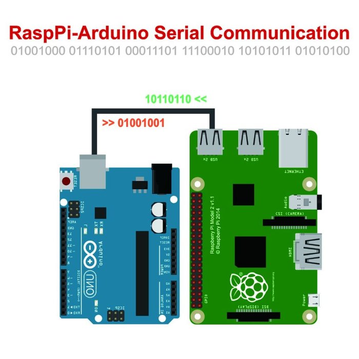
Image reference :
http://www.instructables.com/id/Raspberry-Pi-Arduino-Serial-Communication/
After that, you have to launch the terminal and execute the following commands :
on a first window you type :
roscore
on another window :
rosrun rosserial_python serial_node.py /dev/ttyUSB0
/dev/ttyUSB0 is the usb port the Arduino is connected to so you’ll have to change the «USB0». You can find the name of the port tty* in the Arduino IDE or you can find it in the terminal by typing :
ls /dev/tty*
when you plug the Arduino in the Raspberry port, you can execute this previous command to see which port has been added and thus know which one is the Arduino board.
Finally you can see what the Arduino is publishing on the topic of one of the ultrasound sensors, for example we will try here with the right ultrasound. You can see it by typing on another terminal window :
rostopic echo /ultrasound_right
Publisher
To use ROS in an Arduino script you first have to include some libraries :
#include <ros.h>
#include <std_msgs/Type.h>
You have to replace «Type» with the type of the std message you are using. Here are the different types of std_msgs : http://wiki.ros.org/std_msgs.
You can also use different kind of messages. For instance the ultrasound sensors use :
#include <sensor_msgs/Range.h>
Then you have to start a ROS node (takes care of serial port communications, allows to create publishers and subscribers) with this line :
ros::NodeHandle nh;
You can now create a message object that you will later fill with data and this is the message you will finally publish :
std_msgs::String msg;
where msg is the name of the object. And of course you can choose the type of the message depending on the type of the transferred message.
Then you have to choose if you want to create a publisher, a subscriber or even both.
To create a publisher :
ros::Publisher chatter("chatter", &msg);
This tells that we are going to be publishing a message of the type of the msg variable (with std_msgs::String type) on the topic «chatter». This lets the master tell any nodes listening on «chatter» that we are going to publish data on that topic.
You can now add lines in the void setup() of the Arduino script. You first initialize the node :
nh.initNode()
Next, the following call connects to the master to publicize that the node will be publishing messages on the given topic :
nh.advertise(chatter);
So finally this is what the void setup() in your Arduino code should look like :
void setup()
{
   nh.initNode();
   nh.advertise(chatter);
}
To fill the message object with the data you just have to do this :
msg.data = hello;
where hello is the data you put in your message and hello must have the same type as the msg variable.
You can then publish you message on the topic. To do so you can either publish it once or continually in the void loop() of your Arduino code like this :
void loop()
{
   chatter.publish( &str_msg );
}
Finally you have to add a last line of code in the loop that will call all the callbacks waiting to be called at that point in time :
nh.spinOnce();
Now that you know how each part of the code works you can test a «Hello World» example available on the wiki.ros.org website http://wiki.ros.org/rosserial_arduino/Tutorials/Hello%20World :
/*
 * rosserial Publisher Example
 * Prints "hello world!"
 */
// Use the following line if you have a Leonardo or MKR1000
//#define USE_USBCON

#include <ros.h>
#include <std_msgs/String.h>

ros::NodeHandle nh;

std_msgs::String str_msg;
ros::Publisher chatter("chatter", &str_msg);

char hello[13] = "hello world!";

void setup()
{
  nh.initNode();
  nh.advertise(chatter);
}

void loop()
{
  str_msg.data = hello;
  chatter.publish( &str_msg );
  nh.spinOnce();
  delay(1000);
}
You have to upload this code on the Arduino board before connecting it to the Raspberry and before starting the test on ROS.
Test on a Raspberry
To test it you first have to connect the Arduino board to the Raspberry. Then you launch the terminal and execute the following commands :
on a first window you type :
roscore
on another window :
/dev/ttyXXXX is the usb port the Arduino is connected to and you’ll have to find the exact name in order to replace the XXXX by the name of the port (examples : ttyUSB0, ttyACM0, ttyACM1, ...). You can find the name of the port ttyXXXX in the Arduino IDE or you can find it in the terminal by typing :
ls /dev/tty*
you should first execute this previous command and only then plug the Arduino in the Raspberry usb port and execute this command again to see which port has been added to the list displayed on the terminal and thus know which one is the Arduino board.
The first time you use the usb port the Arduino is connected to, you have to give permissions to use that port. To do so, you have to type :
sudo chmod 666 /dev/ttyXXXX
Now that you know the port you are using and you have permissions, you can type this :
rosrun rosserial_python serial_node.py /dev/ttyXXXX
Finally you can see what the Arduino is publishing on a specific topic by typing on another terminal window :
rostopic echo /topic_name
where you have to replace topic_name by the topic your Arduino is publishing on. In the example above, the «hello world!» is published on the topic «chatter». So you can type :
rostopic echo /chatter
Subscriber
To try this tutorial on you Arduino board you have to connect a Led. The pin used here is the 13 but of course you can change it in the code if you want to use another one.
As in the Arduino Publisher Tutorial you first have to include the libraries. One of them depends on the message you are transferring with ROS. In the following example we will choose an empty message. This means that the message doesn’t contain anything. So when the subscriber receives the message, it doesn’t react depending on its content but it only reacts because a message has been sent. As the type of the std_msg is «Empty», you have to include the following lines at the beginning of your Arduino code :
#include <ros.h>
#include <std_msgs/Empty.h>
Here again, like the Arduino Publisher Tutorial code, you have to start a ROS node with this line :
ros::NodeHandle nh;
Then you initiate the callback function where you have to specify the name of the callback (messageCb), the type of the message (std_msgs::Empty) and the name of the message (toggle_msg which contains the transferred message). The callback is the function called each time you receive a message. If toggle_msg had a content you could use it in the callback but it is not the case here as the message is of type «Empty».
void messageCb( const std_msgs::Empty& toggle_msg){
  digitalWrite(13, HIGH-digitalRead(13));   // blink the led
}
The following line of code is used to instantiate the subscriber. To do so you have to specify two arguments : the topic name (we chose in this example : «toggle_led») and the callback function we defined previously (messageCb).
ros::Subscriber<std_msgs::Empty> sub("toggle_led", &messageCb );
As this is a blink led example, in the setup part of your Arduino code you first have to use the number 13 pin as an output.
pinMode(13, OUTPUT);
Then for the ROS part of the setup you have to first initialize the node :
nh.initNode();
And subscribe to the node you want to :
nh.subscribe(sub);
So finally this is what the void setup() in your Arduino code should look like :
void setup()
{
  pinMode(13, OUTPUT);
  nh.initNode();
  nh.subscribe(sub);
}
Finally you just have to add in the void loop of your Arduino code the following lines where the spinOnce passes arguments to the callback :
void loop()
{
  nh.spinOnce();
  delay(1);
}
Now that you know how each part of the code works you can test the blink led example available on the wiki.ros.org website http://wiki.ros.org/rosserial_arduino/Tutorials/Blink :
/*
 * rosserial Subscriber Example
 * Blinks an LED on callback
 */
#include <ros.h>
#include <std_msgs/Empty.h>

ros::NodeHandle nh;

void messageCb( const std_msgs::Empty& toggle_msg){
  digitalWrite(13, HIGH-digitalRead(13));   // blink the led
}

ros::Subscriber<std_msgs::Empty> sub("toggle_led", &messageCb );

void setup()
{
  pinMode(13, OUTPUT);
  nh.initNode();
  nh.subscribe(sub);
}

void loop()
{
  nh.spinOnce();
  delay(1);
}
You have to upload this code on the Arduino board before connecting it to the Raspberry and before starting the test on ROS.
Test on a Raspberry
To test it you first have to connect the Arduino board to the Raspberry. Then you launch the terminal and execute the following commands :
on a first window you type :
roscore
on another window :
/dev/ttyXXXX is the usb port the Arduino is connected to and you’ll have to find the exact name in order to replace the XXXX by the name of the port (examples : ttyUSB0, ttyACM0, ttyACM1, ...). You can find the name of the port ttyXXXX in the Arduino IDE or you can find it in the terminal by typing :
ls /dev/tty*
you should first execute this previous command and only then plug the Arduino in the Raspberry usb port and execute this command again to see which port has been added to the list displayed on the terminal and thus know which one is the Arduino board.
The first time you use the usb port the Arduino is connected to, you have to give permissions to use that port. To do so, you have to type :
sudo chmod 666 /dev/ttyXXXX
Now that you know the port you are using and you have permissions, you can type this :
rosrun rosserial_python serial_node.py /dev/ttyXXXX
Finally, in order to send a single message to the Arduino, you can publish on a specific topic by typing on another terminal window :
rostopic pub toggle_led std_msgs/Empty --once
where toggle_led is the topic you are publishing on, std_msgs/Empty is the type of the message and we use «—once» to publish this message only once.
Advanced concepts
Custom messages
Robot model
Visualization using RVIZ
Useful packages
Map Server
Navigation stack
Mecanum wheels
We introduced the mecanum wheels in the mechanical part. In this chapter we will review a ROS node we made to control the mecanum wheels.
ROS Twist
In the ROS navigations stack, all movements are indicated by Twist messages. These messages contain linear and angular velocity components and are often used to express the global movement of the base.
To control the 4 motors, we need to convert those velocities in angular velocities for each wheel. In our ROS node, we can define the following function:
def convert(move):
    x = move.linear.x
    y = move.linear.y
    rot = move.angular.z

    front_left = (x - y - rot * WHEEL_GEOMETRY) / WHEEL_RADIUS
    front_right = (x + y + rot * WHEEL_GEOMETRY) / WHEEL_RADIUS
    back_left = (x + y - rot * WHEEL_GEOMETRY) / WHEEL_RADIUS
    back_right = (x - y + rot * WHEEL_GEOMETRY) / WHEEL_RADIUS
We used the inverse kinematic equations presented in the mecanum wheels chapter to convert global base velocity into individual angular velocities.
ROS node
Now that we have a function to transform the twist message, let's setup the node to subscribe to Twist messages and publish individual angular velocity messages to specific topics:
rospy.init_node('mecanum')

# Get parameters about the geometry of the wheels
WHEEL_SEPARATION_WIDTH = rospy.get_param("/wheel/separation/horizontal")
WHEEL_SEPARATION_LENGTH = rospy.get_param("/wheel/separation/vertical")
WHEEL_GEOMETRY = (WHEEL_SEPARATION_WIDTH + WHEEL_SEPARATION_LENGTH) / 2
WHEEL_RADIUS = rospy.get_param("/wheel/diameter") / 2


pub_mfl = rospy.Publisher('motor/front/left', Float32, queue_size=1)
pub_mfr = rospy.Publisher('motor/front/right', Float32, queue_size=1)
pub_mbl = rospy.Publisher('motor/rear/left', Float32, queue_size=1)
pub_mbr = rospy.Publisher('motor/rear/right', Float32, queue_size=1)

sub = rospy.Subscriber('cmd_vel', Twist, convert)
rospy.spin()
In this extract, we initialize the node, get some parameters from ROS' parameter server, define a publisher for each mecanum wheel and
subscribe to the cmd_vel topic where Twist messages are send to. In the subscription, we provide our convertion function as a callback.
This means that whenever a twist message is published on the topic, our function will be called with the twist message as argument.
The only thing left to do is to adapt our function to pusblish the correct values to the corresponding topics.
The code can be found in the Eurobot-2018 repository in the mecanum package
Color detection
The objective of this module is to detect a color combination and send it to the “Minus” robot module whose function is to build a tower made of cubes.
Getting started
Image treatment module
Summary
First and foremost, we must connect to GoPro wifi to take a picture of the color combination. Here, we have chosen a GoPro as a camera because it has an acceptable quality (780 pixel-HD) and it has also a Wi-Fi module for the remote control.
Once the photo has been taken, the camera automatically switches off and we connect to the robot by wifi (a Raspberry connected with the same Wi-Fi for future image treatment).
During this treatment, we use the OpenCV free graphics library.
We have drawn three frames on the picture (one for each cube to detect) to delimit the test portion. The board analyzes all pixels within each frame to obtain the color.
However, we have implemented in our program the different possible combinations to save time. Indeed, we only required two colors to deduce the final combination.
As a matter of conclusion, we send combination to the robot by ROS.
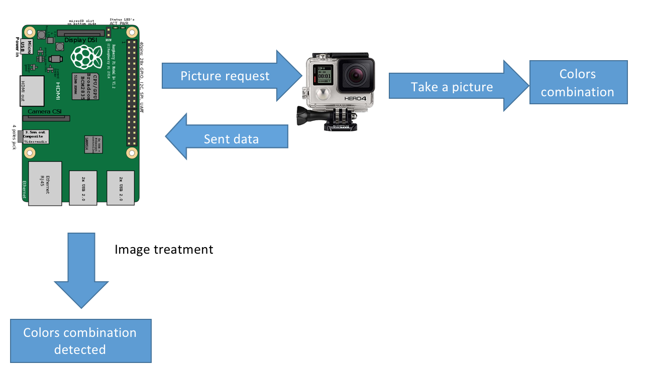
Bill of materials:
- One Raspberry Pi zero W
- One Wi-Fi GoPro (Hero+)
- One 5V battery
- Etcher (https://etcher.io/) to install an OS on the Raspberry
Connections
- No pins required
Setup
- Download last version Ubuntu mate (16.04) or an another distribution for the raspberry (see install)
- Active WiFi and open terminal (alt+ctrl+t):
-
Install ROS (see install)
-
Download this repo from github, unzip Tutorials-master.zip to open the main folder.
-
Drag the folder in the terminal, you'll see a url. Then run this command :
cd "url" -
Run this code above to go to "codes" folder:
cd src/codes/software/image-processing/tests -
Connect the GoPro (WiFi) or your webcam (USB port) to the Raspberry
-
Checking camera
Check your camera is working. Type the following command line into your prompt and press enter :
- Go to "test camera" folder :
cd src/codes/software/image-processing/tests/test_camera
Checking GoPro
We use a library called "goprocam" that contains all functions to control GoPro
-
Run this command to test GoPro in your terminal
python3 go_pro_test.pyMake sure your Raspberry is on the same WiFi network as GoPro !
The code :
#go_pro_test.py

from goprocam import GoProCamera
from goprocam import constants

# Connect to GoPro
gpCam = GoProCamera.GoPro()

# Take a photo and save it in the current folder
gpCam.downloadLastMedia(gpCam.take_photo(0))
Checking webcam
If you don't have a GoPro, you can also use a webcam. Type the following command line into your prompt and press enter :
We use here "OpenCV" library to display and save images from the webcam
-
Run this command to check the webcam
python webcam_test.py
The code :
# webcam_test.py

import cv2

# Create an object called camera and connect the first camera to the computer
camera = cv2.VideoCapture(0)

# Take a photo and save it in the current folder
return_value, image = camera.read()
cv2.imwrite('opencv'+'.png', image)
Result :
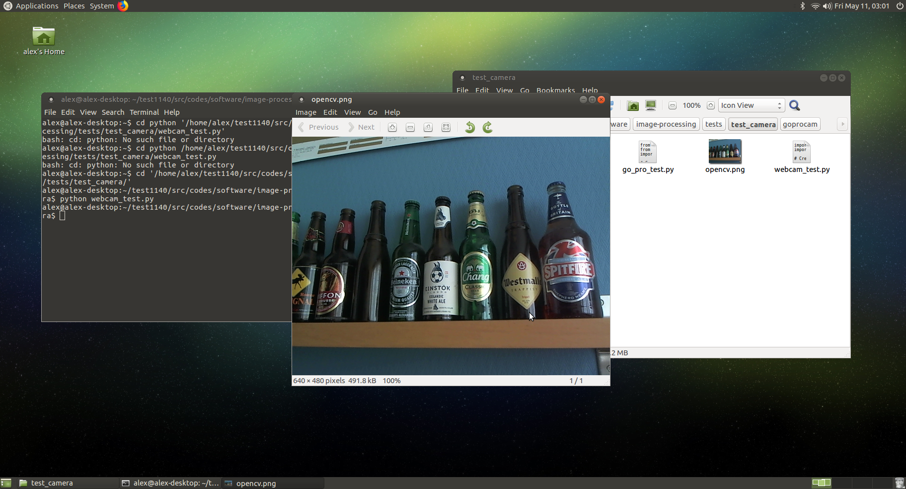
Scripts
After checking the camera, we must run a script to automate the color detection and the WiFi switching (if you use a GoPro).
This script makes three actions :
- To switch WiFi to connect to GoPro to obtain a picture
- To send the picture to the Raspberry to start the image processing
- To give a color combination
Type the following command line into your prompt and press enter to check the settings and run the script
- Go to color_detection folder :
cd ../test_color_detection
- Open GP_combination.sh :
nano GP_combination.sh
- Change the name with your GoPro WiFi :
nmcli c up "your GoPro wifi"
- Change the name with your robot WiFi
nmcli c up "your wifi robot"
save it (ctrl+x)
- Run this script on the terminal :
bash GP_combination.sh
You'll see 3 colors frames on the picture and the final combination color on the terminal)
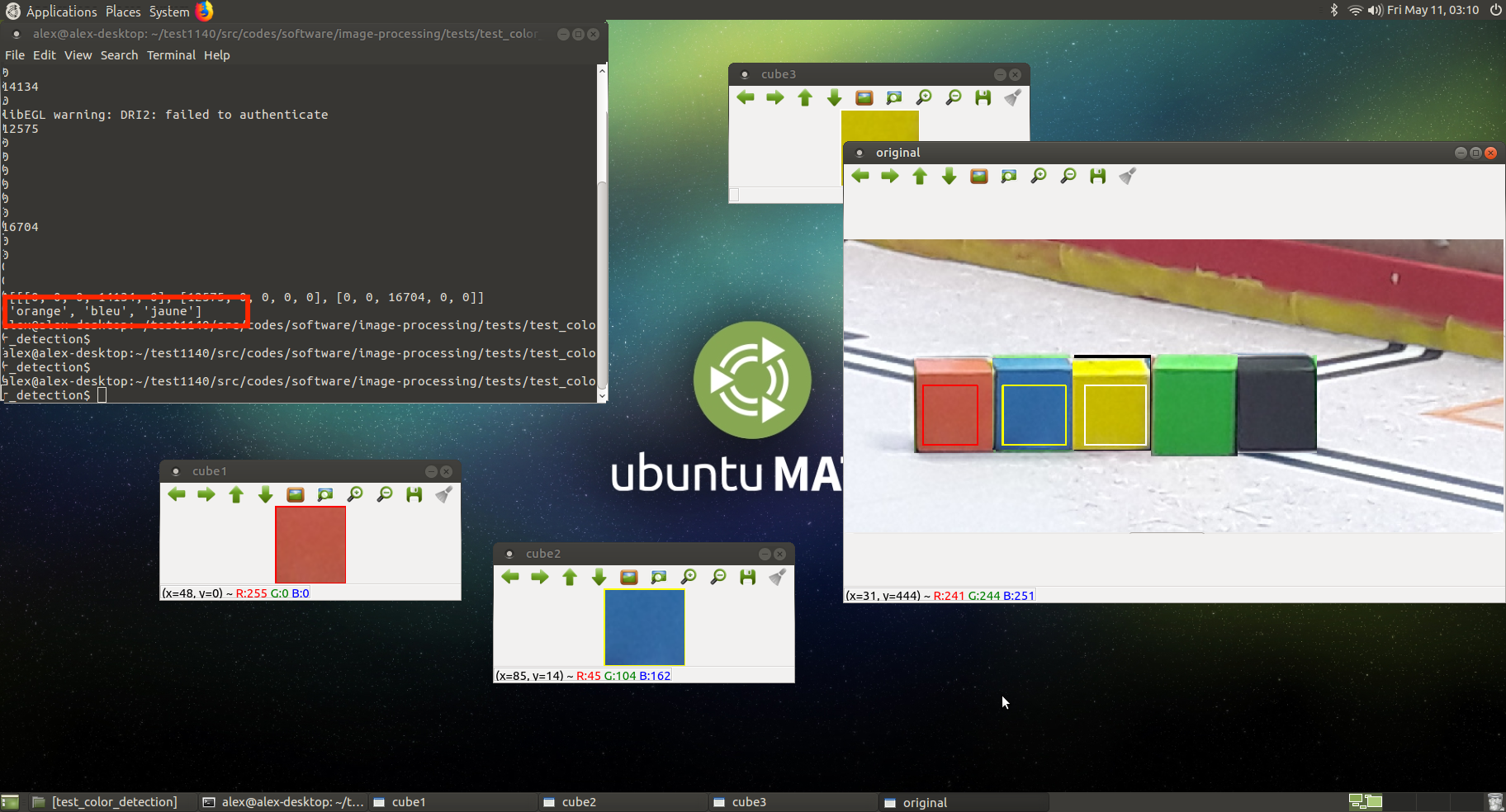
The code :
#GP_Combination.sh

#!/usr/bin/expect

#switch to "GoPro wifi and connect to the GoPro"

nmcli c up "armen"
sleep 10

#Take photo with GoPro
python3 GP_takePhoto.py

#Switch to "robot wifi to connect to minus(robots)

nmcli c up "Airport Express Lenaerts"

#To obtain the color combination
python2 color_detection.py
If you prefer using the webcam instead of GoPro
bash WB_combination.sh
The code :
#WB_combination.sh

#!/usr/bin/expect

python2 WB_takePhoto.py

python2 color_detection.py
Result : The result is the same for GoPro and webcam.
You'll see 3 colors frames on the picture and the final combination color on the terminal as shown in the image below
Image processing - color_detection.py
After taking a picture with the camera or the GoPro, we must process it to generate the color combination : The program creates three frames, one for each cube and analyzes all pixels within each frame:
- It looks whether the color detected is in the range color defined for every color (each color range is defined with one high and one low BGR value)
- After that, it returns a value: more the value is great, more the color lies within the range. The program adds up the values and the final value thus obtained determines the color within the range of colors determined initially.
Adjusting the position of a frame
We must adjust the position of frames to target the part of the image we want to process :
Each position is represented by a matrice. The first value (pixel) is linked with red frame, the second value (pixel) with yellow frame and the last value (pixel) with white frame.
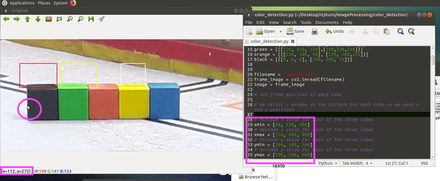
positionName = [red frame value, yellow frame value, white frame value]
Here is the different positions for each frame:
- xmin is the left side of the frame
- xmax is the right side par of the frame
- ymin is the top side of the frame
- ymax is the bottom side of the frame
Procedure :
- Maintain your cursor where you want to place a side of the frame
- Take note of the position (pixel)
- Open a new tab (ctrl+shift+t) and run this command to change a side of a frame in the following code(color_detection.py) :
nano color_detection.py
- Restart for another side of the frame then save the file (ctrl+x)
Result :
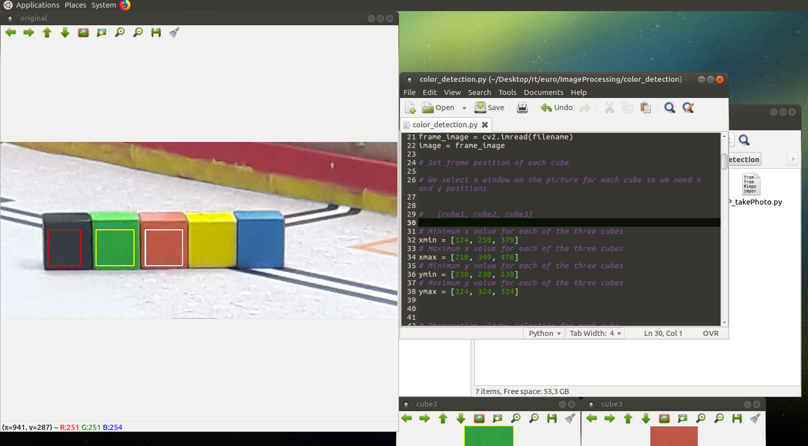
Adjusting the range color
We must adjust the color range (RBG) to define each color. Therefore, the programme will be able to identify differents colors in each frame in function of these RGB values. We represente each color range by a matrix :
color_range = [blue value, green value, red value]
As a reminder, an RGB color value is specified with RGB (red, green, blue). Each parameter (red, green, and blue) defines the intensity of the color as an integer between 0 and 255. For example, rgb(0, 0, 255) is rendered as blue, because the blue parameter is set to its highest value (255) and the others are set to 0.
Procedure :
- Maintain your cursor in the center of the cube
- Take note of the RGB color
- Open a new tab (ctrl+shift+t) and change the color range in the code (color_detection.py)
nano color_detection.py
- Restart for another cube then save the file (ctrl+x)
Result :
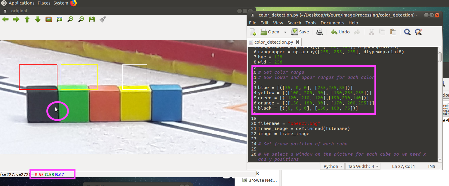
Automation
We have also implemented in our program the different possible combinations to save time. Indeed, we only required two colors to deduce the final combination.
Application with ROS
You use ROS to send the color combination to another robot module :
- Create a package "image-processing" and create a launch files" test.launch" (more details here)
- Drag the code "image-analyze.py"(codes/software/image-processing) to catkin_ws/src/"image-processing"
- Open terminal and launch ROS :
. ~/eurobot_ws/devel/setup.bash
roslaunch image-processing test.launch
- Open a new tab (ctrl+shift+t) to display messages published to a topic :
rostopic echo /color_seq
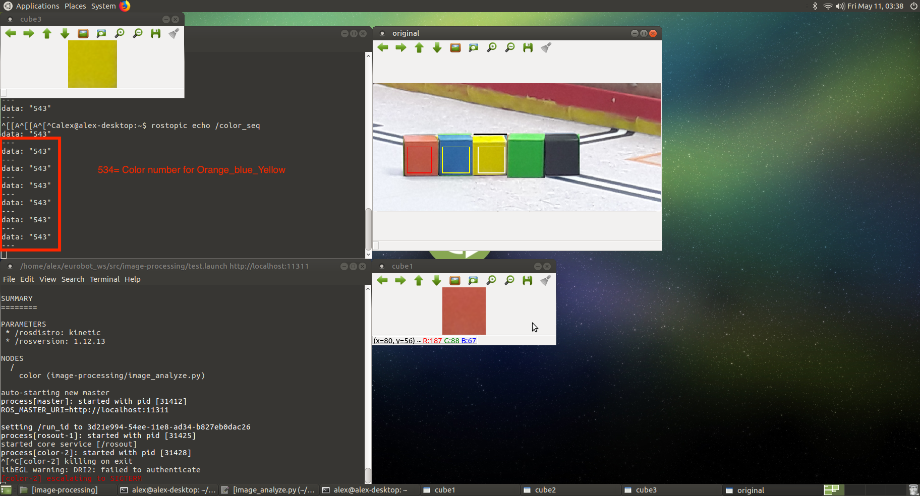
Don't forget to change frames positions and color ranges ! (see section below)
Flashlight module
Aim
We added a LED flashlight above the camera because light is an important factor and can bias our previous calculations. Therefore, the constant level of light thus created enables us to maintain our settings. This flashlight is turned off immediately after the camera has taken the photo, so as not to disrupt other teams or distract the audience.
Bill of materials:
- One Raspberry Pi zero W
- One LED flashlight
- One 5V battery
Connections
We use pin 4 of the raspberry Pi zero to power the gate pin of IRF520 mosfet in order to control the light. The board is powered with a 5V power supply from the battery (pin 2 = 5V and pin 6= GND).
Setup
- for testing the flashlight, run :
python flashlight.py
You'll blink the flashlight
Robots
2018
For the year 2018, the actions robots must perform to earn points are:
- collect blocks of colors to form a turn.
- collect colored balls, sort them by color and send them to several destinations.
- push a bee to explode an inflatable balloon.
- press a button to turn on a screen.
To do so, we decided to design 2 robots, Cortex and Minus.
Cortex is responsible for collecting the balls and pushing the bee and for Minus, collect the blocks and press a button.
In this chapter, we will talk about the general structure of the 2 robots and how to start them.
Folder structure
Here is the general structure of our project for Eurobot 2018.
Eurobot-2018
│   README.md
│   LICENSE
│   .gitignore
└───arduino
│
└───documentation
|
└───ros_packages
|   └───differential-drive
│   |
|   └───differential_driver
│   |
|   └───ecam_msg
│   |
|   └───mecanum
│   |
|   └───navigation
│   |
|   └───robot_2018
│   |
|   └───robot_description
│   |
|   └───sensors
│   |
|   └───strategy
The different folders:
- arduino: This folder contains all the arduino codes used within the 2 robots.
- documentation: The project documentation for the same year of Eurobot.
- ros_packages: Contains all our ros packages.
- differential-drive: Provides some basic tools for interfacing a differential-drive robot with the ROS navigation stack. The intention is to make this independent of specific robot implementation.
- differential_driver: package for the differential drive of Minus.
- ecam_msg: contains custom messages for robots.
- mecanum: package for the mechanic wheels of Cortex.
- robot_2018: package that manages the launch of 2 robots.
- robot_description: package that describes robots for simulation with rviz.
- sensors: packages for ultrasound management.
- strategy: package for the strategies chosen by the 2 robots.
For more information about what is a package in ROS.
Minus
Architecture

There is a raspberry master who talks to the arduinos via the serial port thanks to the rosserial library.
The arduinos who control the motors return the values of the encoders to the rapsberry and the raspberry returns them the speeds to apply.
An arduino takes care of the control of the elevator, the collection of the blocks and sends the values of the ultrasound sensors to the raspberry.
Packages
Differential-drive
Having no time to implement ourselves, a library to manage the differential navigation, we look for an existing library compatible with ROS.
This package provides some basic tools for interfacing a differential-drive robot with the ROS navigation stack.
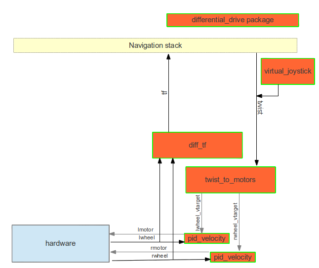
The library therefore needed only 2 input information, the return of the encoders of the left wheel (lwheel) and right (rwheel).
At the exit, we received the speeds of the 2 wheels, lmotor and rmotor.
Setting up the differential-drive package PID controller
The configuration of the package is done via a launchfile containing all the necessary parameters such as Kp, Ki, Kd, etc.
This configuration is in the file
ros_packages/differential_driver/launch/minus.launch
<launch>
  <rosparam param="ticks_meter">16400</rosparam>
  <node pkg="differential_drive" type="diff_tf.py" name="diff_tf">
      <rosparam param="base_width">0.353</rosparam>
      <rosparam param="encoder_min">-1000000</rosparam>
      <rosparam param="encoder_max">1000000</rosparam>
  </node>
  <node pkg="differential_drive" type="pid_velocity" name="lpid_velocity">
      <remap from="wheel" to="lwheel"/>
      <remap from="motor_cmd" to="lmotor_cmd"/>
      <remap from="wheel_vtarget" to="lwheel_vtarget"/>
      <remap from="wheel_vel" to="lwheel_vel"/>
      <rosparam param="Kp">25</rosparam>
      <rosparam param="Ki">10</rosparam>
      <rosparam param="Kd">0</rosparam>
      <rosparam param="out_min">-254</rosparam>
      <rosparam param="out_max">254</rosparam>
      <rosparam param="rate">20</rosparam>
      <rosparam param="timeout_ticks">10</rosparam>
      <rosparam param="rolling_pts">5</rosparam>
      <rosparam param="encoder_min">-1000000</rosparam>
      <rosparam param="encoder_max">1000000</rosparam>
  </node>
  <node pkg="differential_drive" type="pid_velocity" name="rpid_velocity">
      <remap from="wheel" to="rwheel"/>
      <remap from="motor_cmd" to="rmotor_cmd"/>
      <remap from="wheel_vtarget" to="rwheel_vtarget"/>
      <remap from="wheel_vel" to="rwheel_vel"/>
      <rosparam param="Kp">25</rosparam>
      <rosparam param="Ki">10</rosparam>
      <rosparam param="Kd">0</rosparam>
      <rosparam param="out_min">-254</rosparam>
      <rosparam param="out_max">254</rosparam>
      <rosparam param="rate">20</rosparam>
      <rosparam param="timeout_ticks">10</rosparam>
      <rosparam param="rolling_pts">5</rosparam>
      <rosparam param="encoder_min">-1000000</rosparam>
      <rosparam param="encoder_max">1000000</rosparam>
  </node>

  <node pkg="differential_drive" type="twist_to_motors.py" name="twist_to_motors" output="screen">
    <remap from="twist" to="cmd_vel"/>
    <rosparam param="base_width">0.353</rosparam>
    <rosparam param="rate">20</rosparam>
  </node>
</launch>
This launch file assumes your robot:
-
Takes commands for the wheel power on
/lmotor_cmdand/rmotor_cmd -
Publishes the wheel encoder on
/lwheeland/rwheel -
The base_width parameter should be set to the wheel spacing of your robot.
If this is not the case, you can change the mapping in the launch file.
As long as you meet these conditions, and the PID values are sane for your robot, you should be able to drive the robot.
For more information about what is a launchfile. A method for optimizing the PID parameters and calibrating the tick per meter is avalaible there.
Sensors
This package allows us to manage the obstacle detection thanks to the data sent by the ultrasonic sensors connected to the arduino and the action to be performed.
The arduino publishes on various topics (ultrasound_x), the data it receives from the sensors.
The package reads the values and depending on the position of the robot (move_base / feedback) and the values sends a stop message on a topic (obstacle / stop).
For more information about what is a publisher, a subscriber and arduino with ros.
Strategy
In this package, we declare the strategy used by each robot in parameter files.
- initial.yaml: contains the position of the robots at the beginning of the game based on whether we are the red or green team.
- game.yaml: Contains game-specific information such as the duration of a game.
- minus/cortex_actions.yaml: contains the different actions that the robot must perform.
For more information about what is a parameter file.
How to run the robot
Pendant les tests
To launch Minus, just run the main Minus launchfile that is in the robot_2018 package. So just make the following command
roslaunch robot_2018 minus.launch team:=value
If we want to run rviz to see the simulation of the robot just add a parameter.
roslaunch robot_2018 minus.launch team:=value viz:=true
By default, rviz does not start and if we do not set the team parameter, the default value is unknown.
2019
Soja
code
Inside you will find the codes used in the current year's competion.
arduino/motors.ino
This section is used to explain the code used on the Arduino that is used to drive the motors of the big robot and provide feedback of its movements to the raspberry pi. We think this code could be reused with minimal changes the following years as it solves very basic problems that transcend the competition rules.
You can find this code on the 2019 github repository at the following address: https://github.com/Ecam-Eurobot/Eurobot-2019/blob/grand_robot/arduino/motors.ino
| Don't make the mistakes that we did and try to reuse as much code as you can from previous years! | | --- |
The hadware environment in whitch this code is supposed to work is described in the following chapter
That being said let's take a look at what the code does.
Main purposes
This code has 3 main purposes: 1. Receive driving instructions over ROS and translate them to signals to send to the motors 2. Send encoder data back over ROS so we can localize the robot on the map 3. Activate the mechanical arms that we installed for this year's challenge
We also included some debugging functionalities to test the encoders using LEDs for example. But let's not get ahead of ourselves.
First of all, we have to include all the used libraries. This includes the ROS library to subscribe to ROS topic; the servo library is used to control the mechanical arms; a PID library will manage the PID control loop to drive in a straight line and turn around the center of our robot; and finally, various message types that will be used to transfer information over ROS.
#include <FastPID.h>
#include <Arduino.h>
#include <Servo.h>
#include <ros.h>
#include <std_msgs/Float32.h>
#include <std_msgs/Empty.h>
#include <std_msgs/String.h>
#include <geometry_msgs/Vector3.h>
Once this is done, all our used pins and variables have to be declared and defined. We tried to keep the names as self-explanatory as possible. As such, #define c_LeftEncoderPinA 2 means that the first of the two outputs of the left wheel encoder is connected to pin 2 of the Arduino. c_RightMotorPwmPin will be mapped to the pin that will transmit the pulse-width modulated signal that will define the speed of the right motor.
void setup() {
    Serial.begin(57600);

    // init ROS
    nh.initNode();
    nh.subscribe(sub_lin);
    nh.subscribe(sub_rot);
    nh.subscribe(sub_arm);
    nh.subscribe(sub_stop);
    nh.advertise(pub_encoder);
    nh.advertise(pub_feedback);

    pinMode(c_LeftEncoderPinA, INPUT);
    digitalWrite(c_LeftEncoderPinA, LOW);
    pinMode(c_LeftEncoderPinB, INPUT);
    digitalWrite(c_LeftEncoderPinB, LOW);
    attachInterrupt(digitalPinToInterrupt(c_LeftEncoderPinA), HandleLeftMotorInterrupt, CHANGE);

    pinMode(c_RightEncoderPinA, INPUT);
    digitalWrite(c_RightEncoderPinA, LOW);
    pinMode(c_RightEncoderPinB, INPUT);
    digitalWrite(c_RightEncoderPinB, LOW);
    attachInterrupt(digitalPinToInterrupt(c_RightEncoderPinA), HandleRightMotorInterrupt, CHANGE);
    attachInterrupt(digitalPinToInterrupt(c_RightEncoderPinB), HandleRightMotorInterrupt, CHANGE);

    pinMode(c_LeftLedPin, OUTPUT);
    digitalWrite(c_LeftLedPin, LOW);
    pinMode(c_RightLedPin, OUTPUT);
    digitalWrite(c_RightLedPin, LOW);

    pinMode(c_LeftMotorPwmPin, OUTPUT);
    pinMode(c_LeftMotorDirPin, OUTPUT);
    pinMode(c_RightMotorPwmPin, OUTPUT);
    pinMode(c_RightMotorDirPin, OUTPUT);

    if(diff_PID.err()) {
        nh.logerror("There is a configuration error!");
        for (;;) {}
    }

    TCCR2B = TCCR2B & 0b11111000 | 0x01;

    right_arm.attach(c_RightServoPin);
    left_arm.attach(c_RightServoPin);
}
Several variables will contain specific parameters to fine tune the PID loop and others will be used to store useful information such as the number of ticks one encoder has traveled or the messages that will be send over ROS.
After that, we will instanciate certain objects, provided to us by the libraries we included, so we can make use of them later.
We now have to declare our callback functions that are executed every time nh.spinOnce() is called if a new message is received on a ROS topic. "What?!" I hear you say, "We haven't even started ROS or even told it on which topics to listen!". And you'd be right. But we have to declare those functions before we tell ROS what topics to subscribe to because in the same line we also have to point to those callback functions that we are declaring. This is done with a pointer which has to point to an already existing function. So that's why we have to declare the function before we initiate ROS. Pfew! So here we are declaring those functions. Those are lin_cb, rot_cb, arm_cb, and stop_cb, who respectively listen to the cmd_lin, cmd_rot, cmd_arm, and cmd_stop topics. Each of these functions do similar things: first, they expect some object in input. These objects are given to us by ROS and will contain the last message received on the topic. Inside the function we then "unpack" the values from those message objects by assigning their attributes to variables declared earlier. Next, we call an external function that will execute an bction based on what message was received on what topic. Those functions will be written later in the file.
We now arrive at the infamous void setup() function provided by the Arduino. As you all certainly know, the Arduino will execute the code inside this function once right after every boot. In this section we will begin the serial communication needed to communicate over ROS (with a baud rate of 57600 to limit the latency of the channel), initiate ROS, actually subscribe to the topics declared earlier, declare all the in and outputs, as well as this peculiar line:
TCCR2B = TCCR2B & 0b11111000 | 0x01;
What this does is change the Arduino Mega's pwm frequency on pin 9 and 10 to 31.37255kHz instead of the default 490.20Hz. You can find various explanation on the Arduino forum, but the only official Arduino documentation page that somewhat explains this feature is this one.
After this the only other function that is needed for our program to be compilable is void loop(). The code in this loop is actually nothing else than an infinite while(true) loop that the Arduino will keep running over and over again until the end of times. You can see this loop is much smaller than the previous one.
void loop() {
    encoder_msg.x = _LeftEncoderTicks;
    encoder_msg.y = _RightEncoderTicks;
    pub_encoder.publish(&encoder_msg);

    nh.spinOnce();
}
This is pretty straightforward. We set the x and y attributes of the encoder_msg object (whose type is geometry_msgs/Vector3. The z attribute of that oject is not used because we are working on a 2D plane) to the number of ticks the left and right encoder have traveled respectfully. We then have to tell ROS to puplish encoder_msg on the encoder_ticks topic the next time nh.spinOnce() is executed, which happens right after. Optionally, we can also turn our LEDs on or off for debugging purposes here.
We now come to the final section of our code, which is where we declare all the functions that actually tell the motors to turn a certain way or count the number of impulses each encoder is giving in real time. I won't explain the insides of all those functions here, as they could almost all use a seperate documentation on their own.
The essensial thing here is that those functions are not too badly written and work well as they are. There should be no reason to modify them unless there is a change in harware.
rpi/odom.cpp
This file is part of the odom package on the raspberry pi. Its purpose is to listen to messages published on the encoder_ticks topic and use that information to craft an odom message that we can use to localize our robot on a map using RViz.
The whole code is heavily inspired by this question on the ROS forum.
Move package
The move package as it is in the github repository is not quite functional yet. Its purpose was to have a sequence of actions to execute in order ie. dirve forward for 50cm, turn 90° counterclockwise, drive 20 cm forward and activate the arm.
The first thing that we wanted to do is to determine a set of absolute positions to drive to instead of having to tell each action. After losing way too much time trying to understand ROS actions and how to convert a current and target position in the form of an odom message to a set of instructions to be executed by the robot, we came to realise it would be much, much easier to directly have a list of actions to execute. This is exactly what we ended implementing. Unfortunately for us the tournament was only a few days away and we still had many other problems to solve. All this led to some really rushed and unstable code that ended up saving our ass and managed to score just a few points (and even win one match!).
That code has long been burned to the ground and will never be spoken of again. So after that, we were so embarrassed that we tried to rewrite the code a bit better. That code never got quite finished and it is the one that you can find here.
The general idea is that we should listen on some topic for a start message, after wich we send the first command to execute. We then wait for a feedback from the arduino telling us when that command has been successfully executed. Once we receive that signal, we can safely send the next instruction.
rpi/ultrasound.py
In this package, all the data sent by the ultrasonic sensors are read and if the value of one sensor in front on the robot drops below a certain value (10cm in our case), it tells the arduino to pause its current action. Only when all the sensors' readings are acceptable will the robot be able to move. This is necessary for the qualifications of the robot before it can even go on the battlefield.
The way all this is done is pretty simple and works well. Let's analyse this program from the bottom up.
The following lines just tells our program to execute the listener() function defined above.
__name__ == '__main__':
    listener()
Because we have 7 ultrasonic sensors each publishing on their own topic, we must subscribe to those 7 topics individually. In addition, we have to initialise the rospy node and spin it up. This is done respectively with the first and last line of the listener() function.
We also subscribe to the run topic, which we use to make sure the robot doesn't move after the match time is over.
def listener():
    rospy.init_node('ultrasound', anonymous=True)
    rospy.Subscriber('run', String, stop_cb)
    rospy.Subscriber('ultrasound_1', Range, callback, 1)
    rospy.Subscriber('ultrasound_2', Range, callback, 2)
    rospy.Subscriber('ultrasound_3', Range, callback, 3)
    rospy.Subscriber('ultrasound_4', Range, callback, 4)
    rospy.Subscriber('ultrasound_5', Range, callback, 5)
    rospy.Subscriber('ultrasound_6', Range, callback, 6)
    rospy.Subscriber('ultrasound_7', Range, callback, 7)
    rospy.spin()
When a message appears on one of the sensor's topic, it calls the same callback() function with one extra argument. That argument is there so we know which sensor is seeing the data that is being passed. This way we cam make sure that none of the sensors has an obstacle in front of it before we tell the robot it can move.
The way it works is that we declared a list go_condition that contains all boolean values. Each value corresponds to one sensor and is set to True when the sensor is clear and to False if an obstacle is present. Only when each element of that list is True will it continuously send the "start" string to the cmd_stop topic. If that condition is not met, it will send a "stop" message on the same topic. On the Arduino's side, that topic is being listened to and a boolean variable is set which will prevent going into the next iteration of the PID regulation loop and set the motors speed to 0 instead (while staying in that control loop with all other variables unaffected). The effect of this is that when the obstacle is removed and the "start" string is the one bieng published again, the robot simply continues where it had left as if nothing happened.
def callback(data, sensor_num):
    pub = rospy.Publisher('cmd_stop', String, queue_size=10)

    if (data.range < 10 and data.range > data.min_range):
        go_condition[sensor_num] = False
    else:
        go_condition[sensor_num] = True

    if (all(go_condition) == True):
        pub.publish("start")
    else:
        pub.publish("stop")
This other callback function is used to set the first entry in the go_condition list to false if the "stop" message has been received when the time is over.
The effect of this is the same as if one of the ultrasonic sensors had an obstacle in front of it idefinitely, keeping the robot still until everything is reset.
def stop_cb(msg):
    print(msg.data)
    if (msg.data == "stop"):
    go_condition[0] = False
Encoders
An incremental encoder delivers a certain number of pulses per revolution. The number of pulses is a measure for angular or linear movement. A fixed disc on a shaft is divided into transparent and opaque segments

Source : https://instrumentationtools.com/encoder-working-principle/
Most of them have two rows of segments (track A and track B) and a Top Z segment. The two tracks out of phase by 90° indicate the direction of rotation, while the top Z indicates the number of revolutions.

Their resolution is the maximum number of pulses it sends per turn, it is expressed in tick/tr (in the encoder that we use we have 4000 ticks/tr).
Material:
Model: Baumer ITD 01 B14 Incremental Rotary Encoder
The datasheet of this encoder is avaible.
Color Assignment
Green --> Track A
Yellow --> Track B
Brown --> V+
White --> GND
Transparent --> Shield/Housing
We decided to plug the wire on this way for all the encoders:

To facilitate the wiring, we made a PCB to connect the encoder to the Arduino Mega. Here the pin mapping of the encoders:
Right Encoder: green (track A) --> pin 2 yellow (track B) --> pin 3 Left Encoder: green (track A) --> pin 19 yellow (track B) --> pin 18
Shield
On the shield we have two connectors for the encoders, one connector to plug with the H-bridge and one that can be connected to the battery in case the Arduino is not connected by USB cable to the Raspberry.
We also soldered two LEDs that allow us to verify that the encoders move the code and perform the position calculation.

You can see how we connect the shield to the H-bridge.

Warning!! This documentation is only for the new version of the PCB not the old one!
Things that weren't quite finished and other research directions for next year(s)
move.py
As said earlier, the move package is something that has to be redone from scratch.
use of feedback message
The first thing that should be done to have a basic, functioning robot is to try to edit the python file so that it only sends the next command when a message is received on the cmd_feedback topic.
wait for start instruction
After that it could listen for a message published somewhere by the node managing the starting rope before sending the first command.
ROS actions
Once all that is working and the robot can move around like it should, only then can you begin to research what ROS actions are and try to use that instead of topics to send commands to the motor-driving Arduino. One good thing with ros actions is that they provide feedback and are preemptible as where we had to implement those features in our own (objectively worse) way to achieve a similar functionality with topics.
The way it is implemented now required us to fake an ultrasound sensor to stop the robot after the match time was over. This is obviously a bodge and could be implemented in a much better way.
Development process
Git & github
Git and especially github are magnificent tools when used correctly. At the start of the project, it would be a good idea to make sure everyone knows how to clone, fork and contribute to a repository. Everyone involved in the project should know what a branch is and what can be done with it.
Github projects
This year we used Trello and microsoft Teams to plan the whole project out and to share files. Github now proposes similar features directly integrated with the codebase. You can even assign certain cards to issues linked to specific files or commits. It could be worth the time to investigate if and how such a tool could be of any use to manage a project like this (spoiler: it probably is). In any case, using Teams to share code is certainly a very bad idea. That is the exact reason source control was invented in the first place. It could however still be useful to share very large binary files like VM images or to store backups of the raspberry pi's sd card.
Graphic chart

Colors
The used colors in HEX format :
- Blue : 012D5A
- Yellow : FFC72C
Fonts
The fonts are available on https://dafont.com
- ECAM : SF Distant Galaxy Italic
- Robotics : SF Distant Galaxy Outline Italic
- Brussels : Open Sans
- ENGINEERING SCHOOL : Open Sans Bold
The polo
The polo were manufactured by 4eme dimensions : http://www.4dimension.be/.
The vector file is available here : XXX
The poster
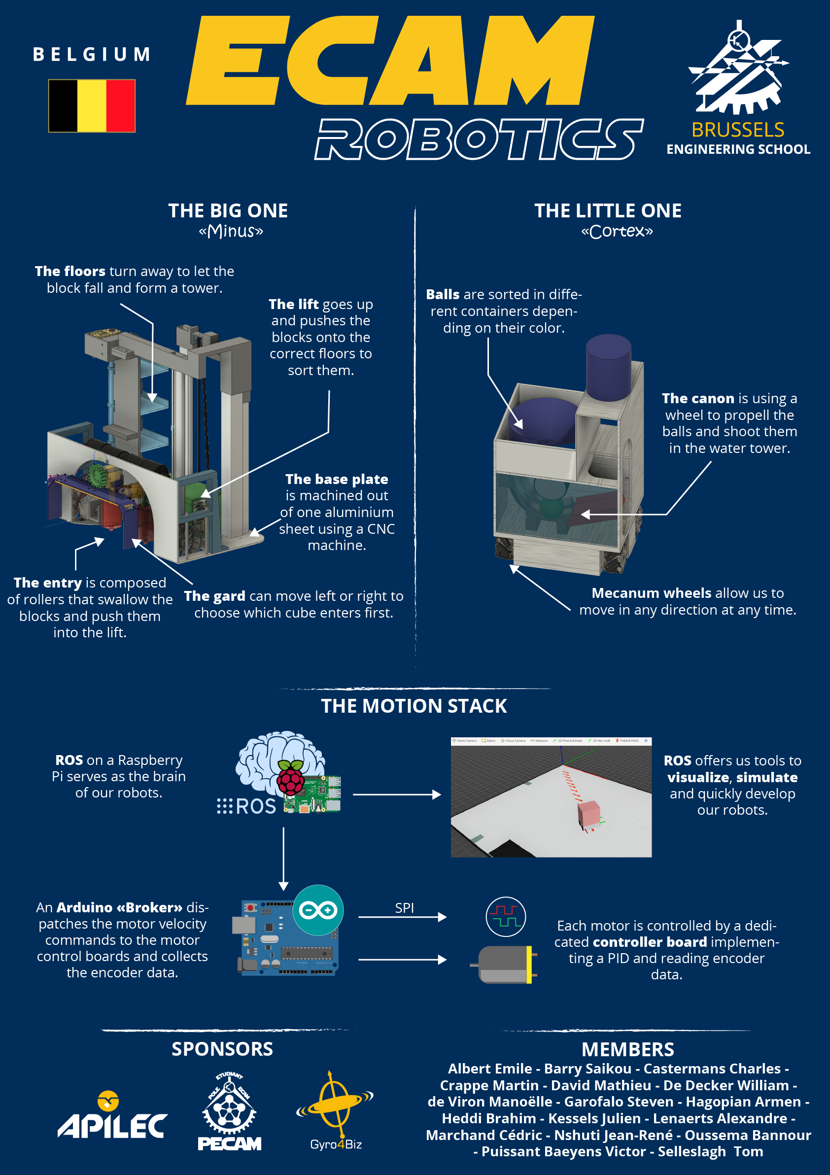
The poster was printed by Graphoprint-services-europe in A0.
The vector file is available here :
Files
The Adobde Illustrator files of the polo and the poster are available on the github.